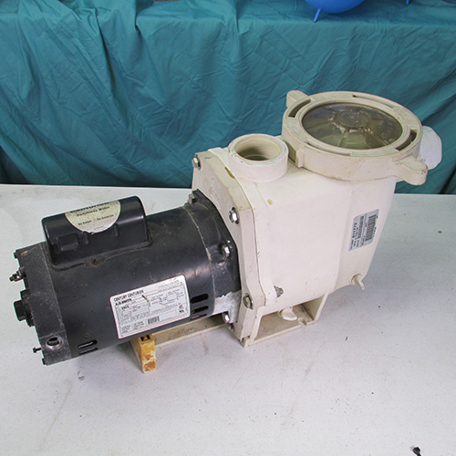
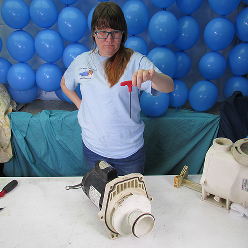
How To Change the Motor on a Pentair Whisperflo Pump
Step by Step Instructions
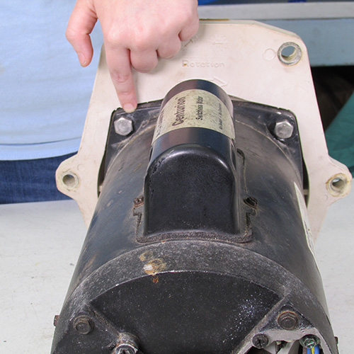
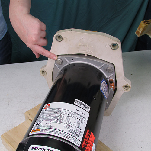
Step 1
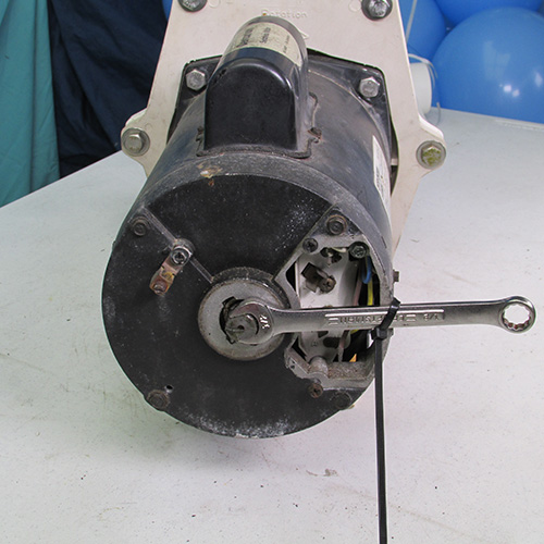
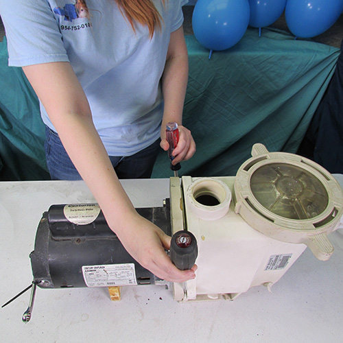
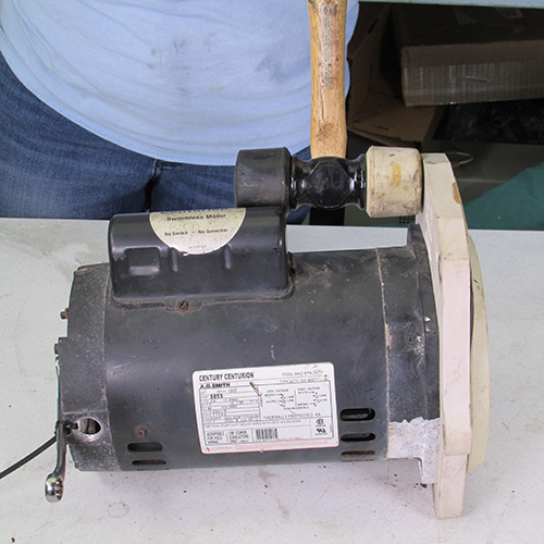
The first thing we do on this motor is remove the rear cap that is covering the shaft extension. This will allow us to gain access to the shaft to enable us to lock it from turning.
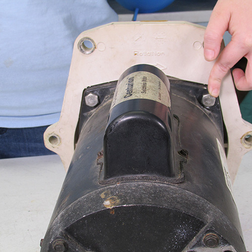
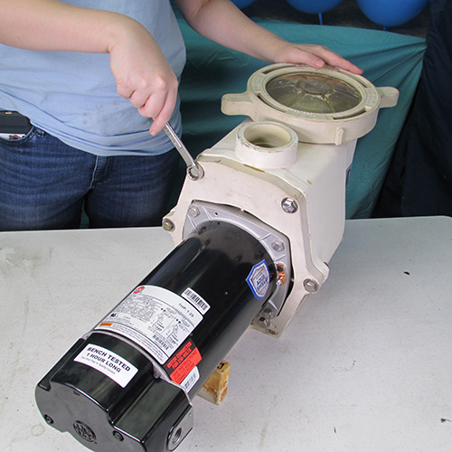
Step 2
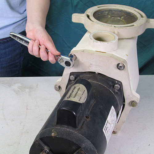
After removing the cover, we slide a 1/2" open end wrench over the flats on the end of the shaft and tie the wrench to the motor casing with a zip tie as shown in this picture. Alternatively you can use vise-grip locking pliers to hold the shaft.
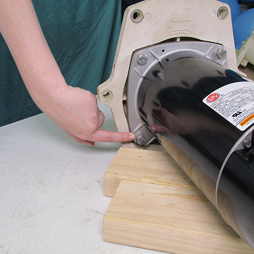
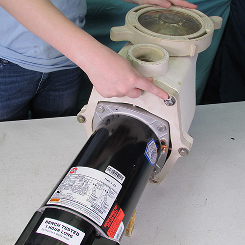
Step 3
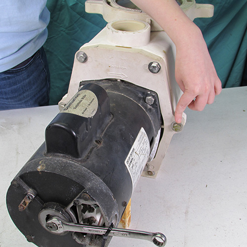
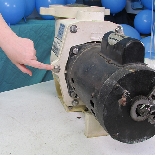
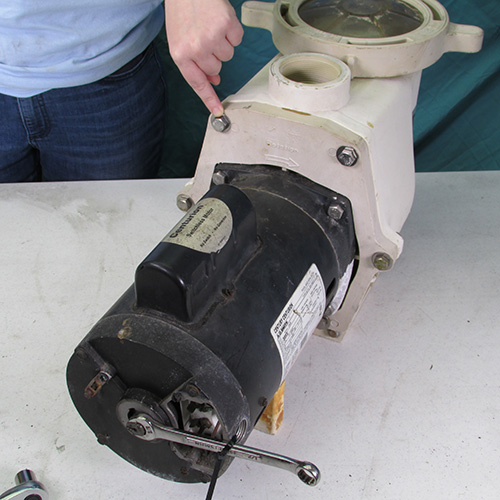
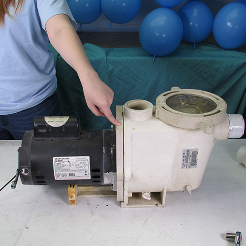
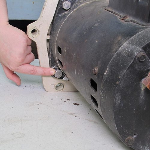
In the next step, we want to remove the six 9/16" bolts as shown in the next series of images.
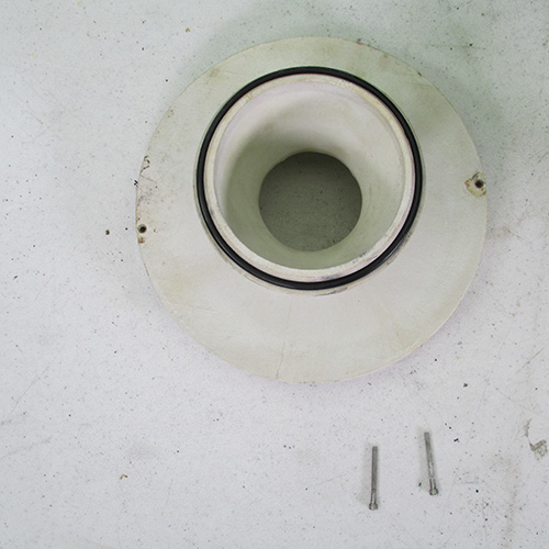
Here is how the six bolts look when they are removed. Notice that two of them are longer and have locking nuts. Save these for later.
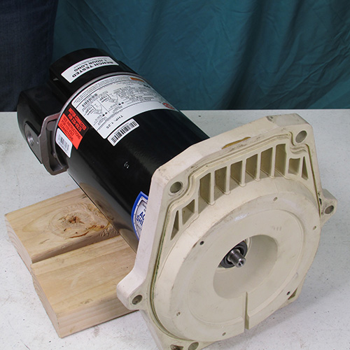
Step 5
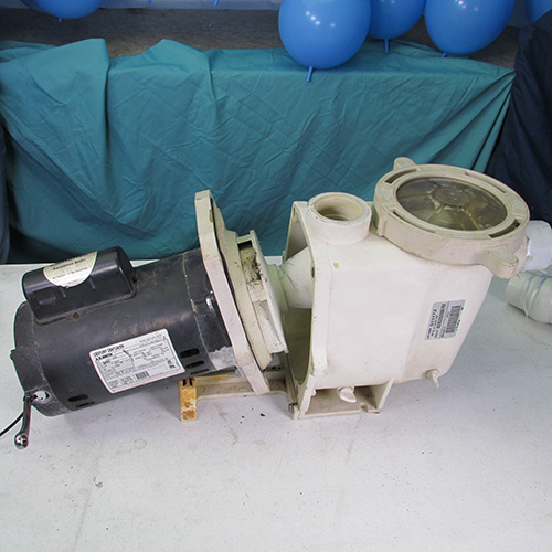
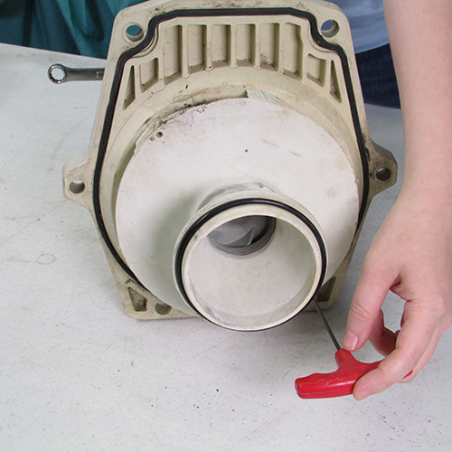
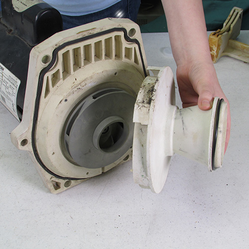
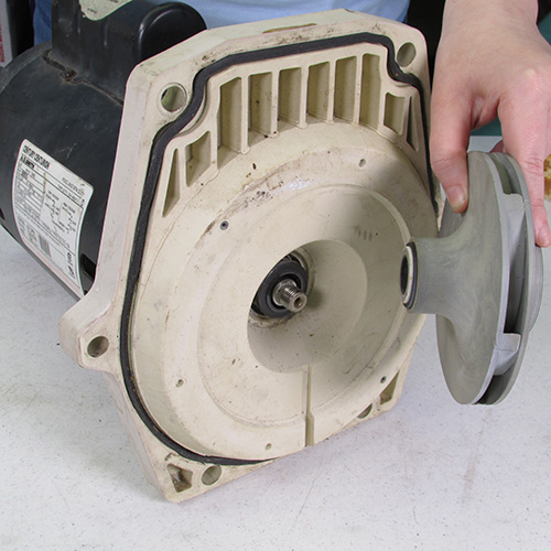
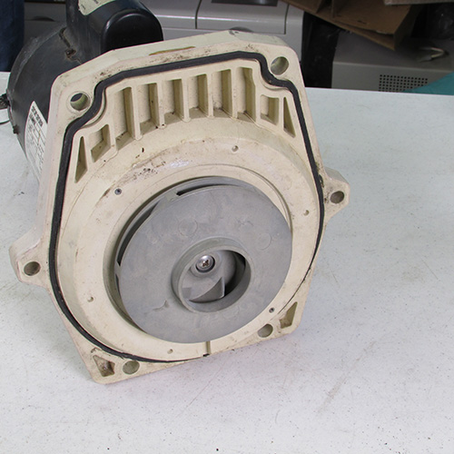
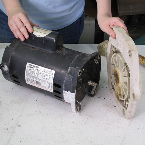
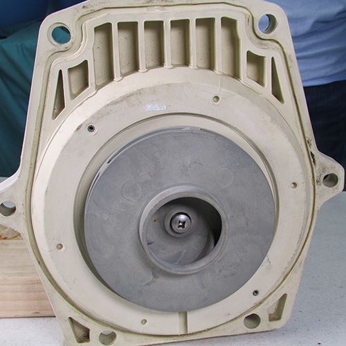
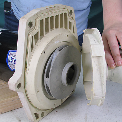
After we have removed the 6 bolts the next step is to separate the power unit containing the motor and the impeller from the wet end assembly. Normally, in a real world situation the wet end assembly will be connected by plumbing and left in your yard. For this demonstration we are removing it on the bench.
Step 6
After removing the two diffuser screws simply pull off the diffuser as shown.
Step 7
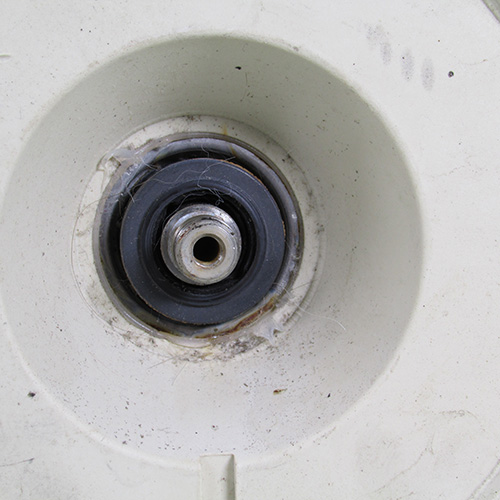
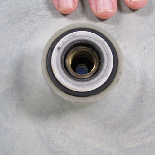
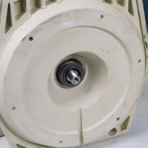
Once the impeller is loose you remove it by turning it in a counter clockwise direction exposing the seal as shown.
Step 9
This is the carbon ring portion of the seal that is pressed into the seal plate also known as the seal head assembly.
This is the seal ceramic ring assembly that is located in the impeller also known as the seal seat.
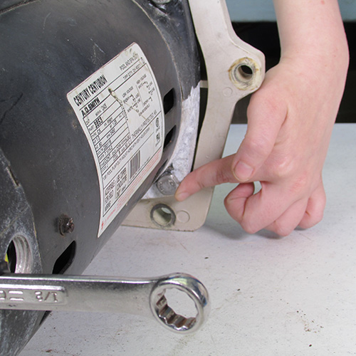
The next step is to remove the four 9/16" bolts as shown. These can be removed with a 9/16" wrench. It is very important to keep these bolts separate from the others as they are shorter and if you put in a longer bolt you will damage the seal plate. We recommend keeping the parts in small paper cups so you know where they belong when you re-assemble.
Step 10
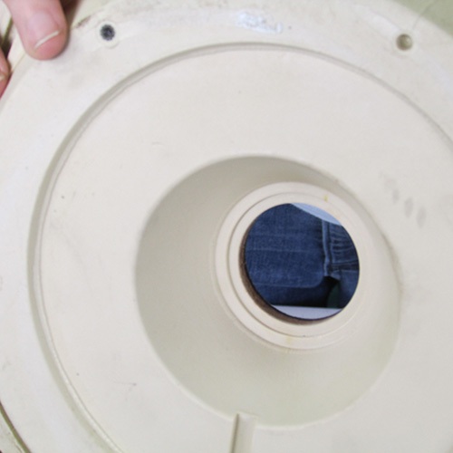
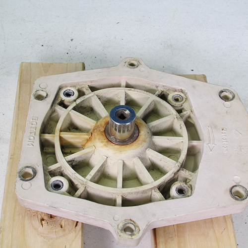
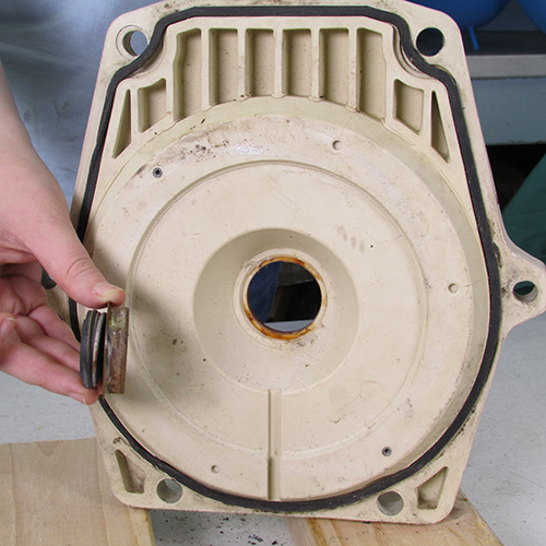
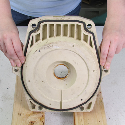
This is what it looks like when the seal plate is removed from the motor.
Step 11
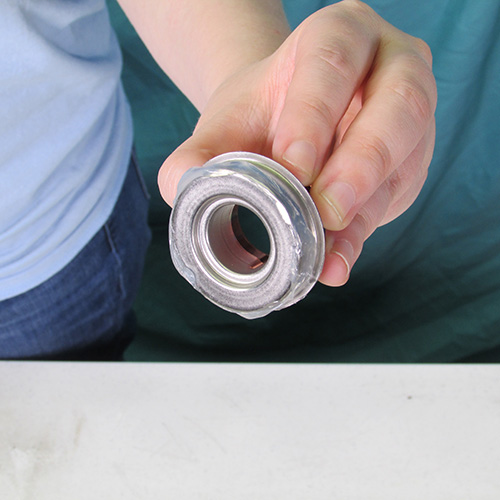
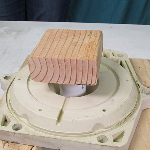
The next step is to remove the seal head assembly from the seal plate. This is accomplished by using a socket and a block of wood as shown.
When that is done successfully the seal should come out and look like this.
Step 12
VERY IMPORTANT
Carefully inspect the seal plate for any damage or distortion caused by heat or any cracks or fissures. Inspect both sides very carefully also check the inserts where the four bolts attach to. If there is any problems or discrepancies with the seal plate you must replace it. Installing a new motor on a defective seal plate will result in short term failure of the new motor. Most likely the manufacturer will not cover it as a warranty item because water damage caused by seal failure is excluded by most manufacturers warranties.
Place a small block of 2x4 on top of the PVC coupling as shown.
Gently strike the block which will in turn drive the seal into the seal plate. Always use body and eye protection when using these tools.
Next we do a careful inspection of the installed seal to make sure the seal plate did not get cracked or damaged and that the seal head itself did not get broken or cracked.
Step 18
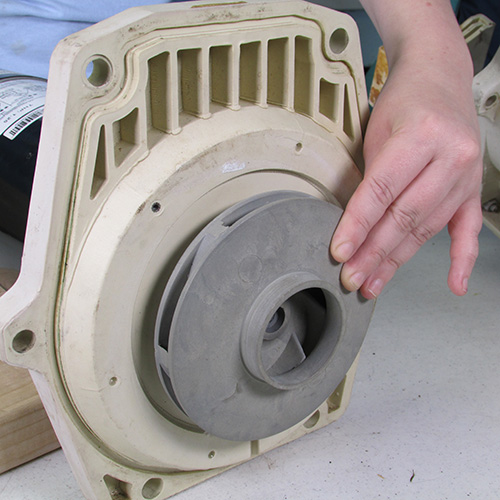
Next we will reinstall the seal plate on the new motor.
Step 19
We will insert the four short bolts that we saved previously. Put them thru the motor as shown in the next images.
Gently tighten them up with a 9/16" wrench.
This is what it should look like from the front at this step.
Close up
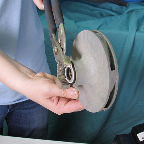
The next thing to do is to remove the seal seat from the impeller.
This is accomplished by using channel lock pliers or alternatively it may be pried out gently with a couple of small screwdrivers. Be very careful not to break the impeller when removing this seal.
Step 20
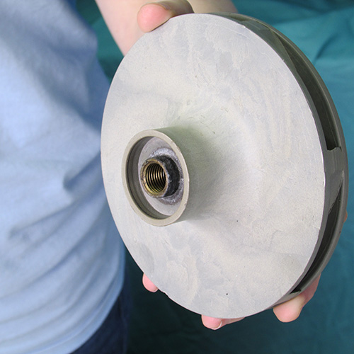
This is what it looks like when the seal has been removed.
Step 21
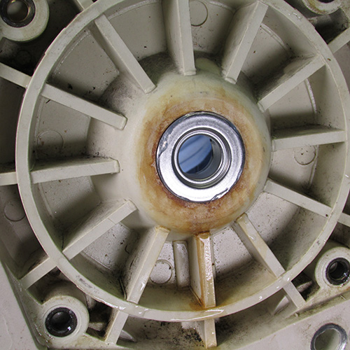
VERY IMPORTANT
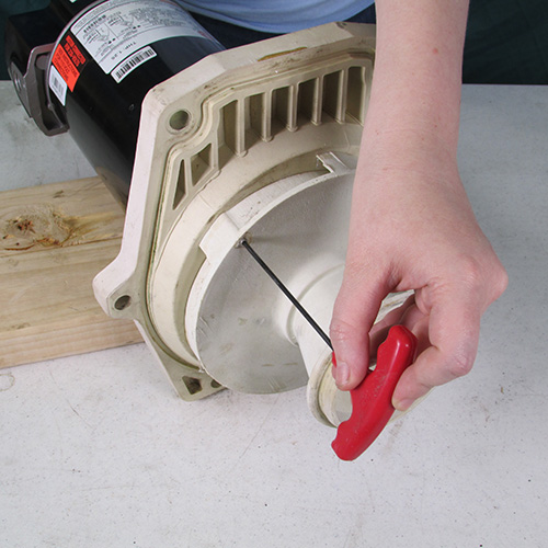
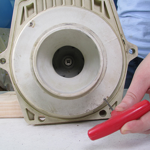
Inspection --- inspect the impeller for any damage. If there is any debris in the vanes use a piece of stiff wire such as a old coat hanger and dislodge and clean out the debris. Check where the seal seat is installed and look for any evidence of melting or distortion
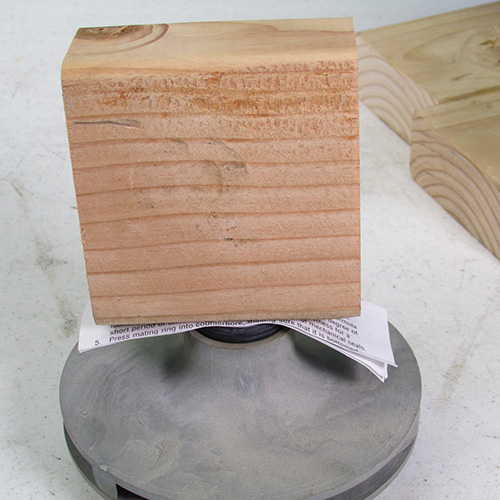
Step 22
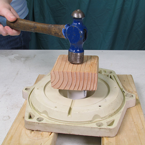
Place a piece of paper on top of the seal surface and place a block of wood on top of the paper as shown and gently press the seal into place.
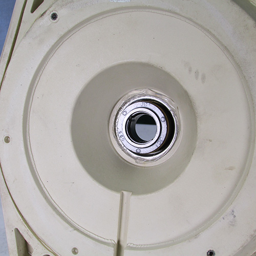
Step 23
This is how the seal seat should look after installation.
Step 24
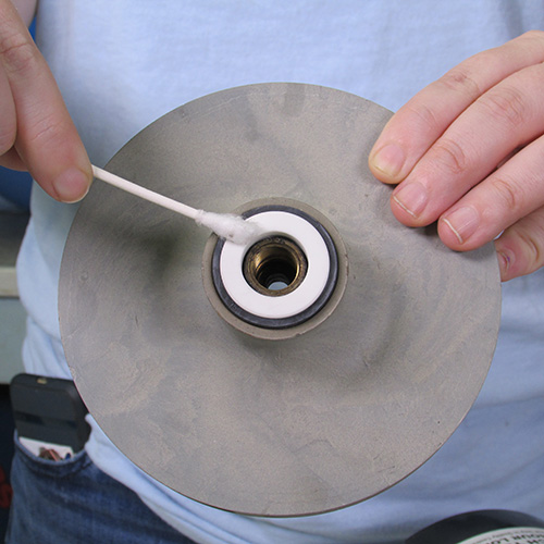
Using a Q-Tip saturated with alcohol clean the carbon surface of the seal very carefully. This is a very important step.
Step 25
Using a Q-Tip saturated with alcohol clean the ceramic surface of the seal.


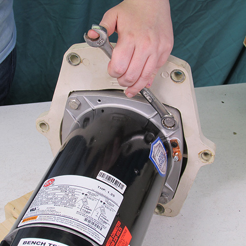


Step 4
Use a 9/16" wrench to loosen and remove all 6 bolts.
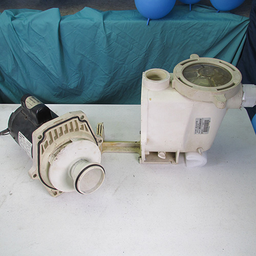
Gently insert two screwdrivers in the crack of the housing as shown and gently pry the units apart. Be very gentle and go slow.
This is how it looks when the power unit is separated.
Acquire a 3/32" Allen key wrench you will need this to remove the diffuser.
Using the 3/32" Allen key wrench remove both diffuser screws as shown.
This is a image of the diffuser removed with the screws. Put this aside and save it for later.
In this step we will proceed to remove the impeller.
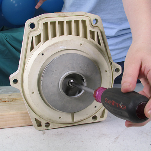
The first thing we will do is remove the impeller locking screw by inserting a #3 Phillips screwdriver in the screw located in the center of the impeller. This is a left hand thread screw so to remove it we will turn it to the right. (or clockwise)
Once it is loosened up gently pull it out.
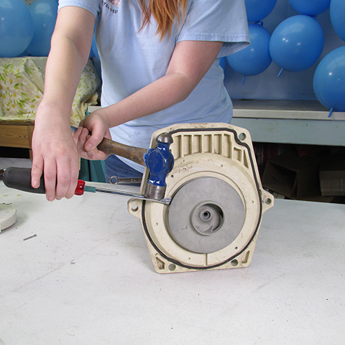
Step 8
Next we must remove the impeller. The impeller is threaded on to the motor's shaft and must be turned counter clockwise or left to remove it. Some impellers come off easy and some impellers are stubborn. We found one of the easiest ways to remove an impeller is to insert a very large slotted screwdriver into the vanes at the outer diameter of the impeller and strike it with a large hammer. The resulting impact force will loosen up even the most difficult impeller. We have found this method to be more reliable than the conventional methods such as large channel locks and strap wrenches. Be careful when doing this so as not to damage any of the pump components. Always use body and eye protection when using these kind of tools.
After removing the four bolts, the next step is to remove the seal plate assembly. This is done by gently tapping the seal plate with a soft rubber mallet or alternatively a block of soft wood. Do not strike the seal plate with a metal hammer.
Place the socket on the seal and the wood on top of the socket and gently strike it with a hammer.
If you determine the seal plate is good during your inspection then you can wash it and reinspect it. If all looks good then continue on.
Step 13
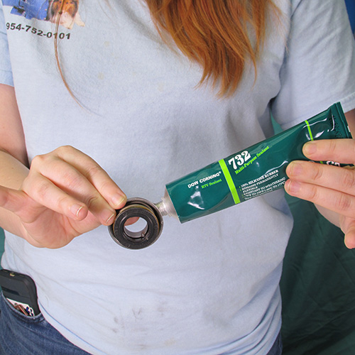
Apply a thin bead of RTV silicone around the periphery of the metal portion of the seal as shown. Do not over do it. Do not get any of the silicone RTV on the black or carbon part of the seal. If you do immediately clean it off with some alcohol.
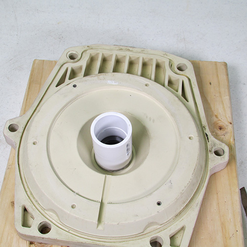
Carefully set the seal into the seal plate as shown.
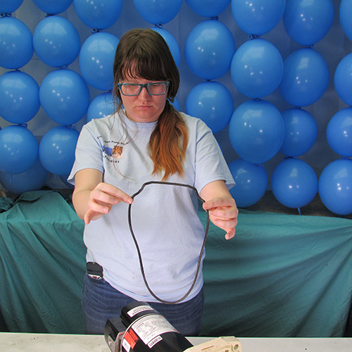
Use a 1" PVC coupling as a seal installation tool as shown.
Step 14
Step 15
Step 16
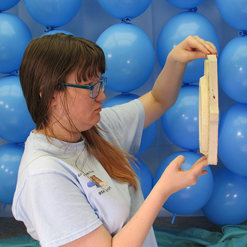
Step 17
Inspect both sides carefully and thoroughly.
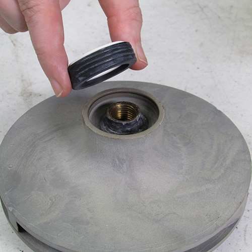
Insert the new seal into the impeller as shown you can lubricate the rubber part of the seal with soap and water. Do not use grease, oil, WD40, Magic Lube, or any petroleum products. Use only soap and water to lubricate the seal.
Step 26
Install impeller onto motor shaft as shown rotate clockwise. Turn hand tight.
Step 27
Remove rear cover on new motor.
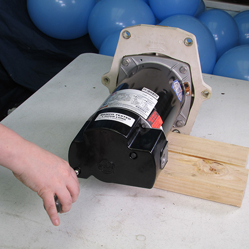
Step 28
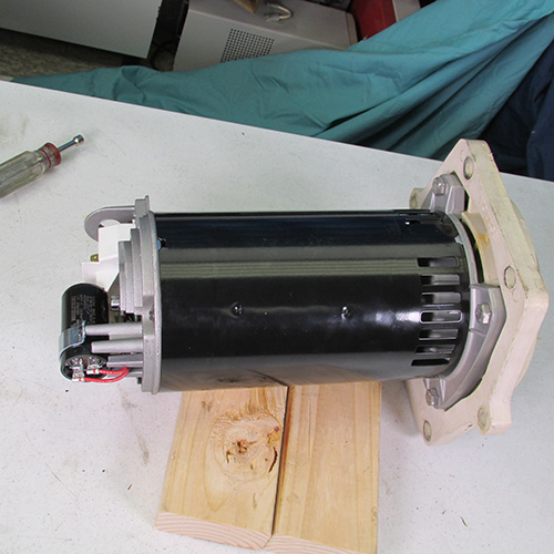
Turn motor upside down and support on blocks.
Lock rear of motor with 7/16" wrench to prevent shaft from turning.
While holding shaft wrench with one hand tighten impeller by turning clockwise with the other hand. Hand tight is sufficient.
Re-install back cover.
Step 29
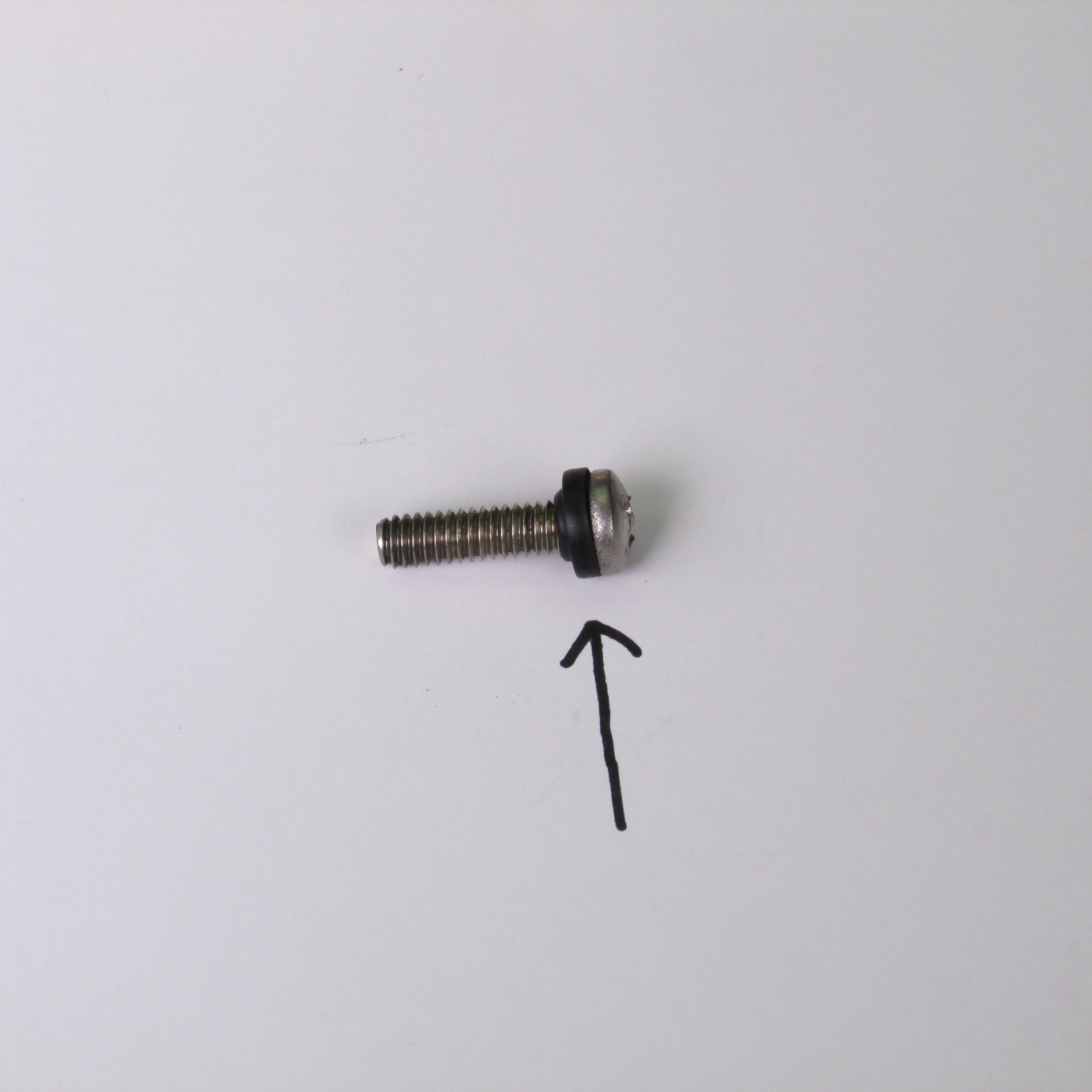
Re-install left hand thread screw by turning counterclockwise or left Pay particular attention that the little rubber washer is in place under the screw head. If this is missing replace it. Do not assemble the pump without this washer.
Turn the screw by turning it counter clockwise or to the left using a #3 Phillips screwdriver.
Position and re-install the diffuser.
Step 30
Tighten the diffuser screws with the 3/32" Allen wrench.
Step 31
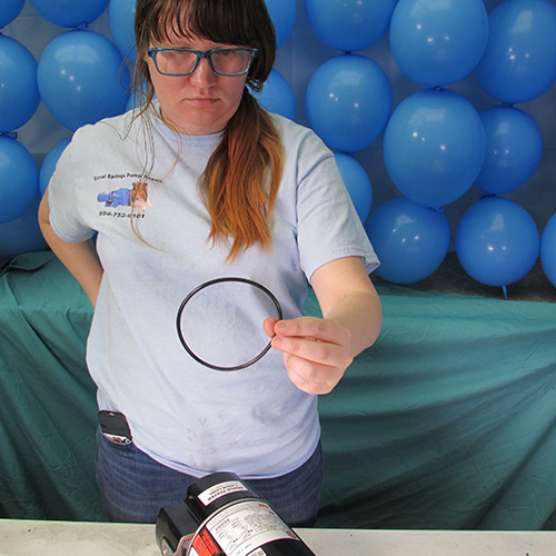
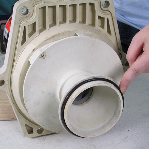
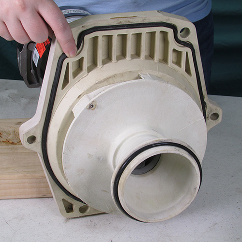
Replace all the O-Rings.
Step 32
Once the O-Rings are in place you can lubricate them with Magic Lube.
Slide the power unit into the wet-end as shown.
Step 33
Tighten the six bolts as shown.
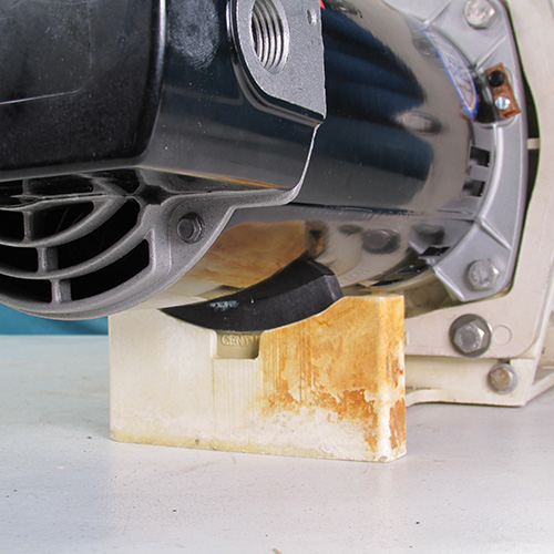
Insert a rubber spacer under the motor near the pump base.
Close up of spacer.
Replace lid O-Rings and lubricate with Magic Lube.
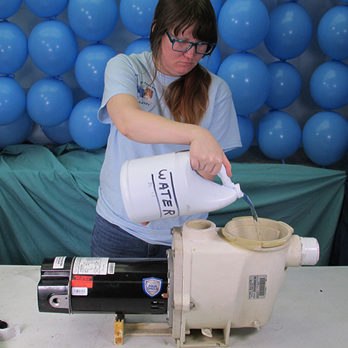
Fill pump basket with water before running.
All images are available in high definition format by right clicking and opening a new tab. This will enable you to do a close up inspection of the images.

Bolt 1
Bolt 2
Bolt 3
Bolt 4
Bolt 5
Bolt 6
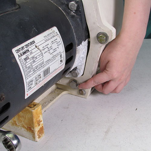
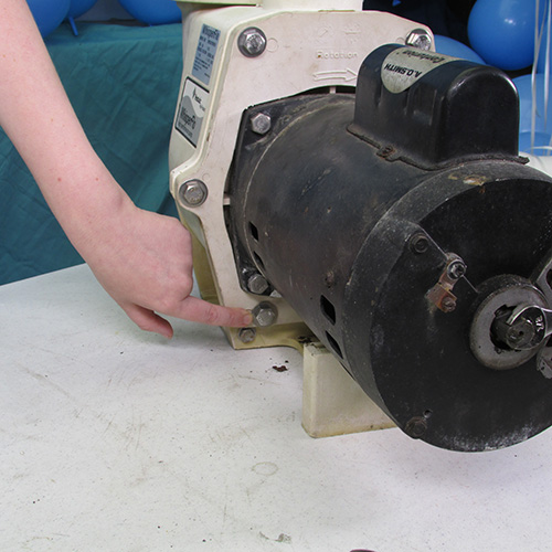
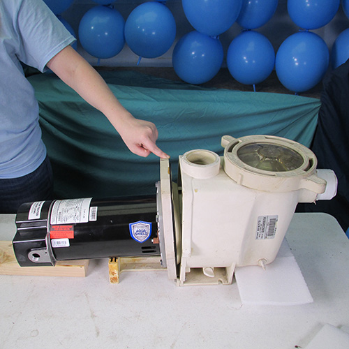
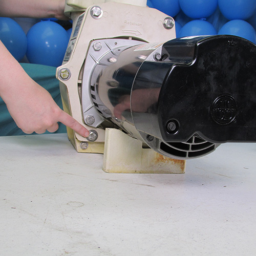
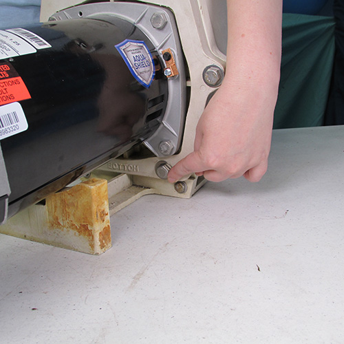
Do Not Remove the 4 Bolts
around the motor at this time! That will be done later