


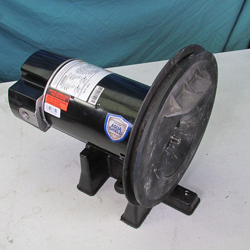


How To Change the Motor on a Sta-Rite Duraglass Pool Pump
Step by Step Instructions
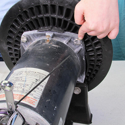
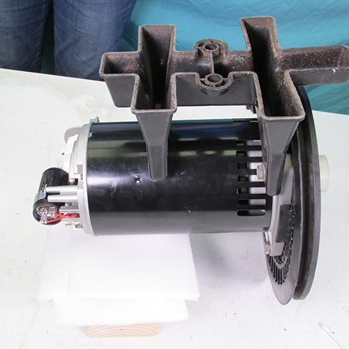
Step 1
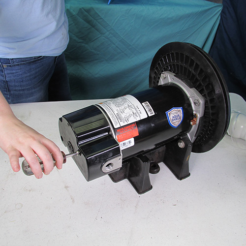
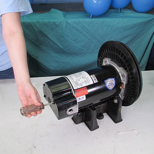
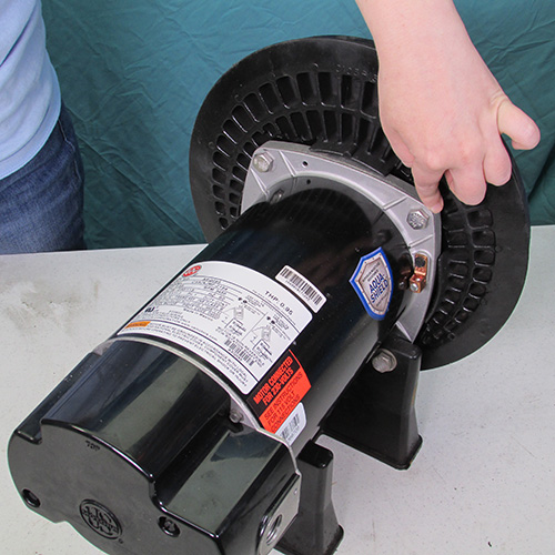
The first thing we shall do is remove the two screws holding the rear cover of the motor in preparation for removal of the rear cover.
Step 2
We shall now remove the rear cover by sliding it backwards. If it is stubborn or stuck we can gently tap it off by sliding a screw driver or chizzle in the seam between the motor housing and the back cover and gently tapping rearward at multiple locations around the periphery.
Step 3
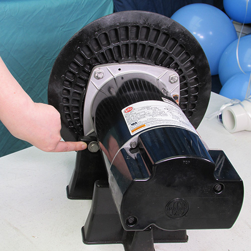
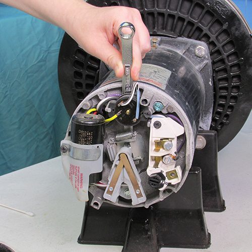
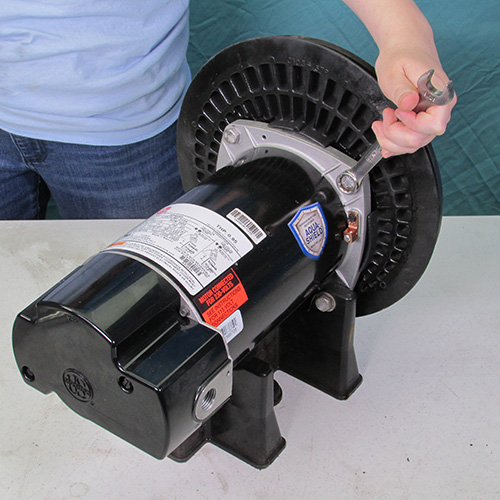
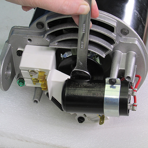
After removing the rear cover, the next step is to lock the motor shaft so it will not turn. We do this by inserting a 7/16" open end wrench behind the over load switch and extending downward behind the governor as shown here.
Step 4
Once we have inserted the wrench around the shaft we attach a ziptie as shown to secure the wrench to the motor and prevent it from falling out. This makes it much easier for one person to accomplish this task.
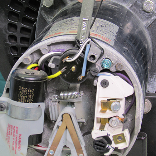
This is a close up of the wrench that is attached by the ziptie to the post protruding from the motor.
Step 5
The next thing to do is to remove the locking knob on the stainless steel band. This is done by turning it counter clockwise. On some pumps there will be a 7/16" nut instead of the knob. In which case you would use a 7/16" wrench to remove it.
Step 6
Once the knob or nut is removed the next step is to remove the stainless steel locking band. It may just gently slide off or if it is stuck you may have to gently pry it with a couple of large screwdrivers. Be gentle and careful so as not to damage the pump housing.
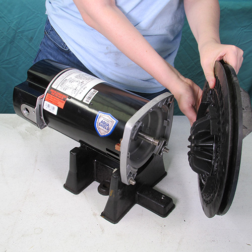
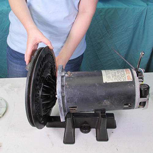
Step 7
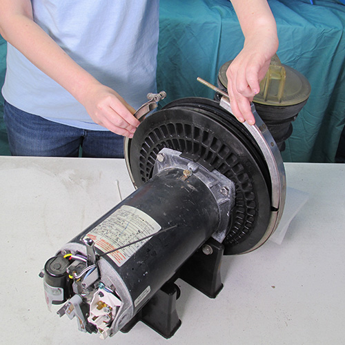
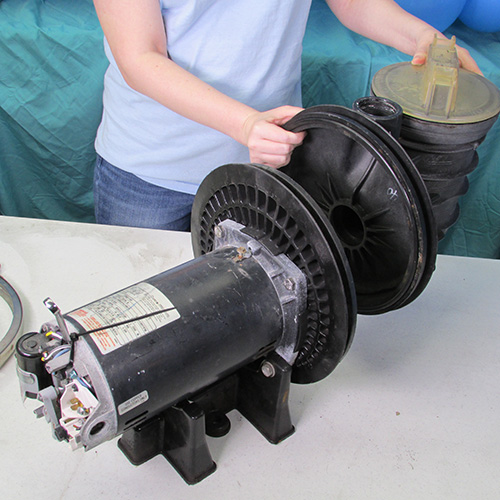
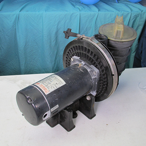
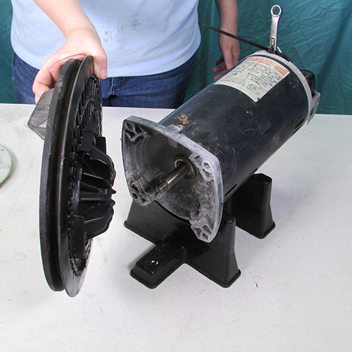
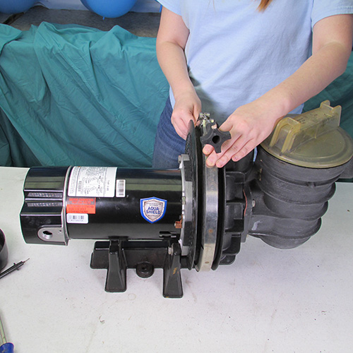
Next we will separated the motor and power unit from the pump wet end assembly. This is accomplished by grasping the motor and pulling backwards. Sometimes you may have to use a couple of screwdrivers at the seam to pull back the power unit. In any case, be careful and gentle when using these tools.
Step 8
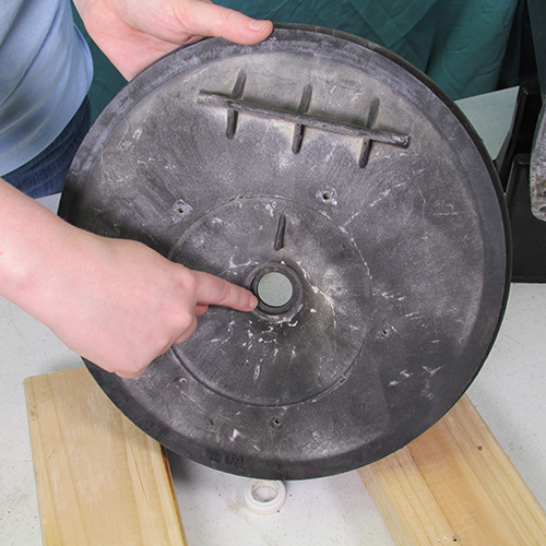
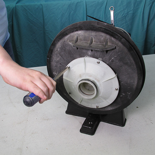
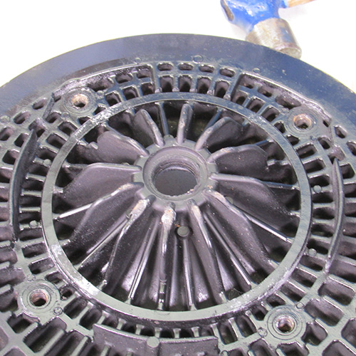
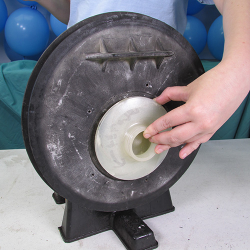
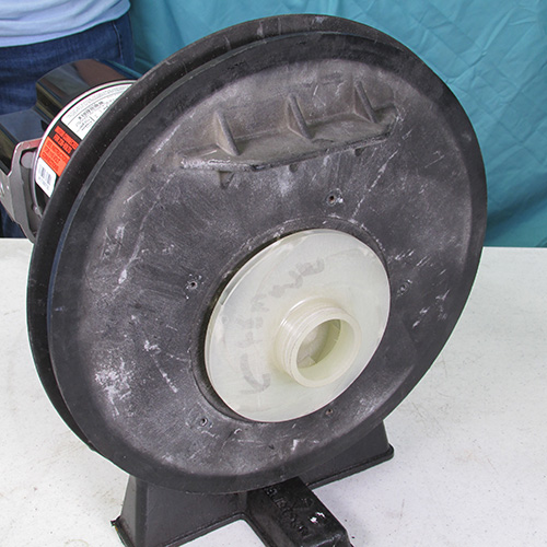
In this step we shall remove the diffuser. This is accomplished by removing the 5 screws around the outer diameter of the diffuser as shown.
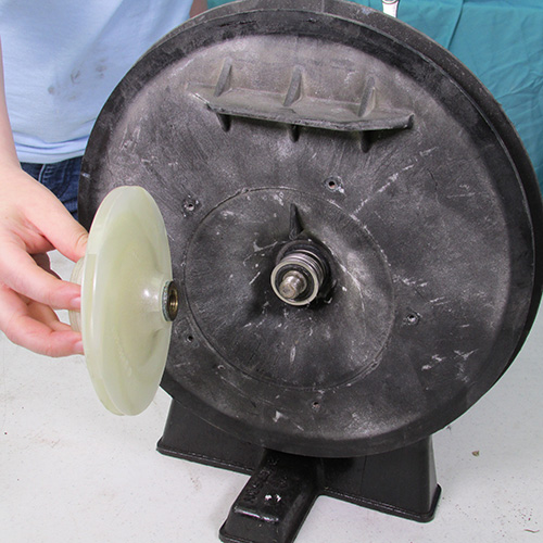
Step 9
Once the diffuser screws are removed, we should be able to remove the diffuser by simply pulling it forward.
Step 10
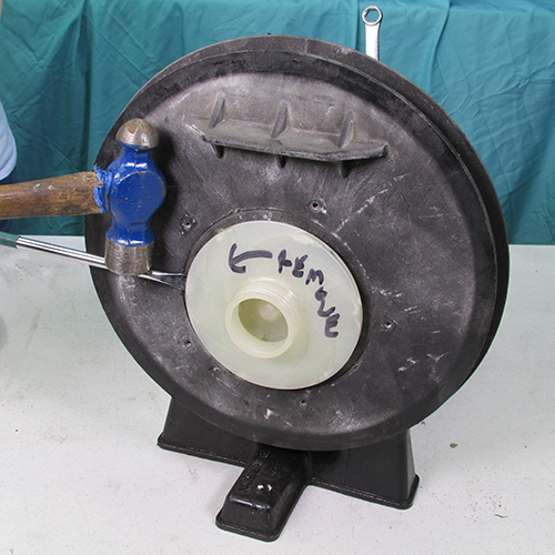
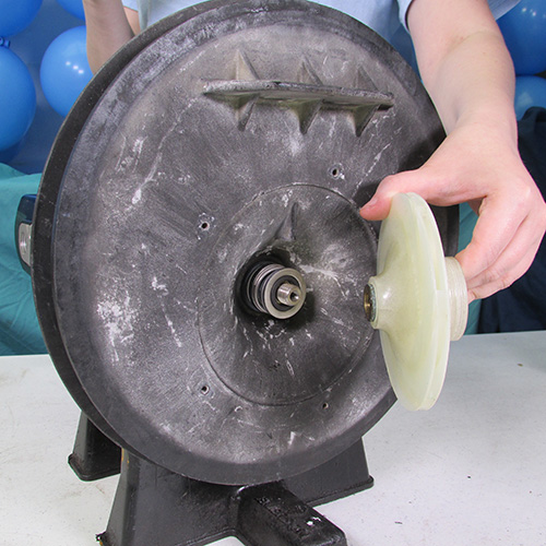
Now we have to remove the impeller. This may be simple and easy or it may be more difficult. The first thing to do is to try and grasp the impeller with your hand (preferably wearing gloves) and turn it counter clockwise or to the left. If this is successful, continue turning it until it comes off. If it does not come off easily then you can try removing it with large channel locks or a strap wrench. A method that we found very successful is to insert a very large flat bladed screwdriver into the edge of the impeller and strike the end of the screwdriver closest to the impeller with a hammer in the counter clockwise direction. The impact force of the hammer will usually jar loose the most stubborn of impellers.
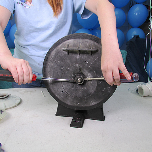
Step 11
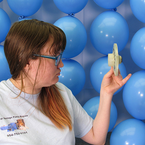
After removing the impeller the next step is to remove the pump seal. One method of doing this is to take two very large screwdrivers insert them behind the seal as shown and attempt to pry it off. In severe cases it may be necessary to break up the seal assembly with a sharp chisel by inserting it parallel to the shaft end and breaking it up in several pieces.
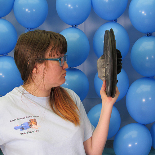
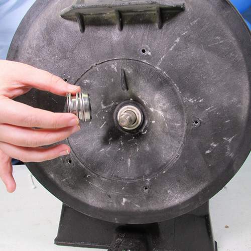
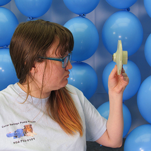
This is what the seal looks like when it is removed.
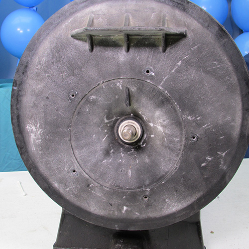
This is the seal seat located in the seal plate.
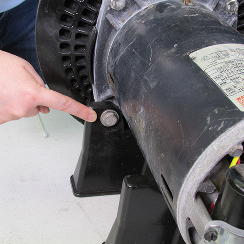
Step 12
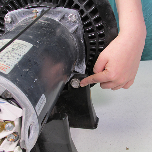
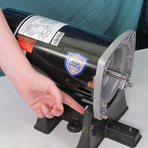
Next we shall remove the four 9/16" bolts that hold the motor to the seal plate. There are four of them as indicated in the pictures.
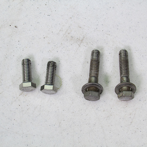
This is what the bolts look like when they are removed. Note that two of them are short approximately one inch long and the other two are about an inch and a half long. It is very important when reassembling the unit to put the short bolts on the top and the long bolt on the bottom as they past thru the lower plastic base assembly. Be sure to pay attention to this when you reassemble because if you put it together incorrectly you can damage an expensive seal plate.
Step 13
After the bolts are removed, we can remove the seal plate assembly from the motor it will usually just slide off. However, if it is stuck a gentle tap with a soft mallet of piece of wood will dislodge it. Do not use a metal hammer.
Step 14
If you're going to replace the motor with a new one, you can remove the 7/16" wrench from the rear and discard the motor. However, if you are just doing a seal replacement then just put the motor aside for re-installation.
Step 15
In this step we will remove the seal seat from the seal plate assembly.
Invert the seal plate and support it on a couple of 2x4's as shown.
Using a solid screwdriver gently tap the seal seat out of the seal plate as shown.
Step 16
VERY IMPORTANT
Make a very thorough inspection of the seal plate assembly especially in the area where the seal seat was removed. Look for any evidence of distortion or melting caused by heat damage the seal seat flange surfaces should be neat and square if there are any discrepancies replace the seal plate. Do not install a new motor and new seal on a defective seal plate it will not last long and will ultimately cause destruction of the new motor and the motor manufacturer will probably not cover it under warranty as they will cite water damage caused by seal failure as a warranty exclusion. It is important to inspect both sides of the seal plate and look for cracks or other imperfections. If the seal plate looks good then you can continue on.
This is the critical area of the seal plate that you will really want to inspect.
Step 17
Take your new motor out of the box and set it on the base and insert the two longer bolts that we indicated earlier on the bottom two holes of the motor and base assembly as shown.
Set this aside for now.
Step 18
Take your new pump seal and lubricate the rubber ring on the seat assembly (the white part) with a mixture of soapy water or approved rubber lubricant like p80 if you have some. Do not use oil, grease, magic lube, wd40, or anything other than soap and water.
Step 19
Lubricate the seal plate as shown
Step 20
Place the seat of the new seal in the bore of the seal plate as shown and press firmly into the seal plate with the butt of a clean screwdriver.
Step 21
Carefully inspect the front and the rear of the seal plate with the new seal installed and be sure it is seated properly and not crooked.
Step 22
We will recover the motor that we set aside previously and set the seal plate with the new seal seat installed on the face of the new motor and we will install the remaining two short upper bolts and the longer lower bolts which is thru the base as shown.
We will tighten these up with a 9/16" wrench.
This is what it will look like once the seal is installed.
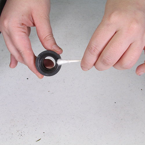
Step 23
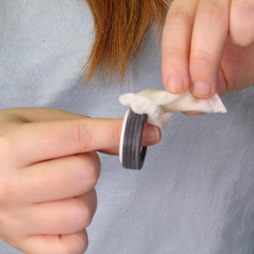
Using rubbing alcohol and a cotton q-tip it is necessary to clean both seal surfaces very carefully this is a very important step as failure to clean the seals before assembly will result in a short service life. Once you clean the facings do not touch them with anything.
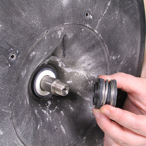
Step 24
Carefully place the seal head assembly on the shaft as shown using due care to be sure that the mating ring does not come in contact with the shaft. (this could damage it)
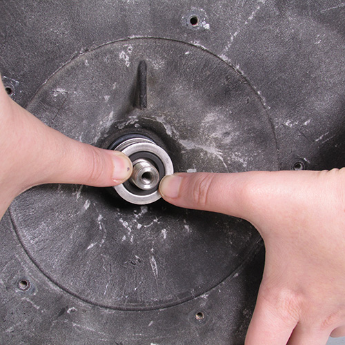
Step 25
Carefully press the seal on to the shaft as shown.
Step 26
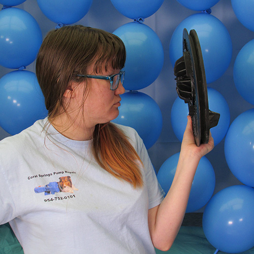
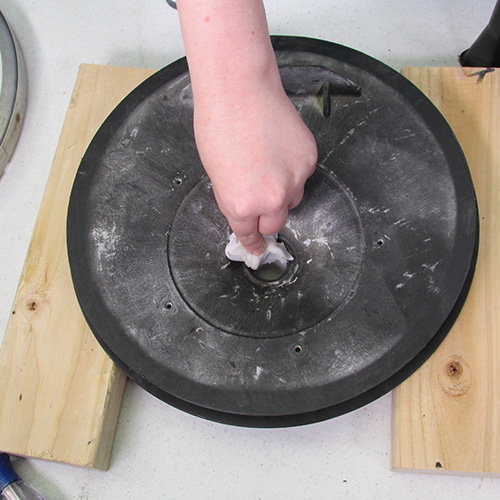
Carefully inspect the impeller for any cracks or damage and also check to see if there is any debris in the vanes if there is remove it with a stiff wire.
Step 26
If the impeller looks good we are now ready to replace it on to the shaft as shown. Turn the impeller in a clockwise direction and tighten it hand tight for now.
Step 27
Remove the back cover of the new motor in preparation so that we can lock the shaft.
Step 28
Turn the motor and pump upside down and prop it up on a soft material so as not to scratch the motor.
Step 29
Insert a 7/16" wrench to lock the shaft as shown.
Close up
Step 30
While holding the 7/16" wrench with one hand turn the impeller clockwise and tighten up securely. (hand tight is enough)
Step 31
Reinstall the back cover on the motor.
Step 32
We will now re-install the diffuser as shown.
Step 33
Tighten up the 5 screws holding the diffuser to the seal plate.
Step 34
Install new O-rings on the diffuser and main body and lubricate them with Magic Lube or a Teflon or silicone based lubricant. Do not use a petroleum based product.
Step 35
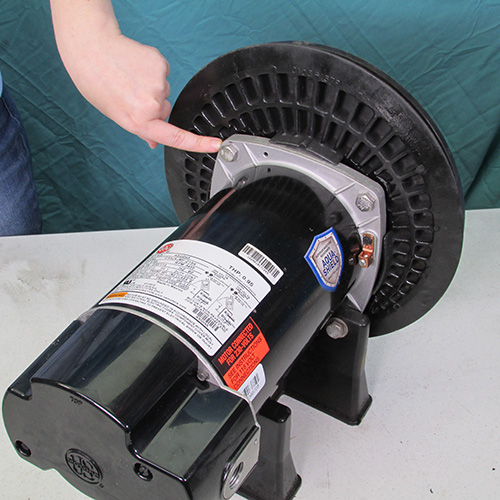
Slide the rear power unit into the front housing as shown.
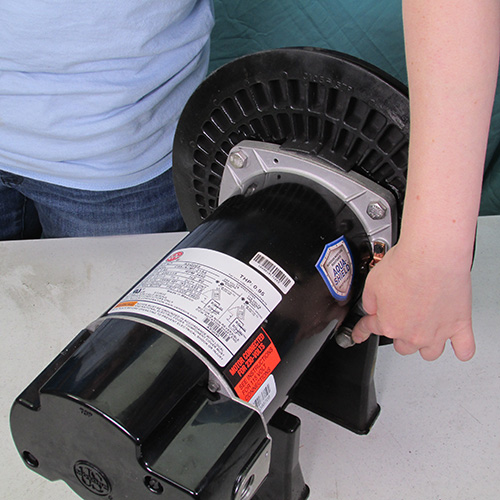
Step 36
Attach the stainless steel mounting band as shown and tighten the knob or nut firmly.
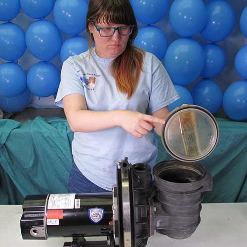
Step 37
Install a new O-ring on the pump basket lid as shown and lubricate it with Magic Lube.
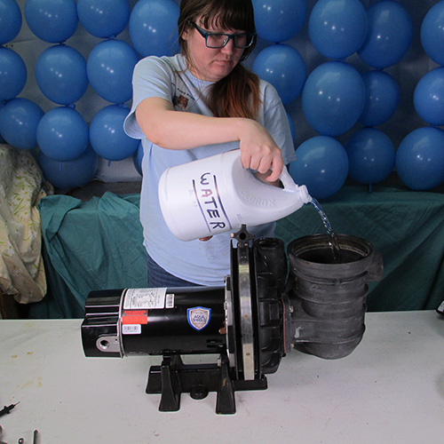
Step 38
Be sure to fill the housing with water before running
This instruction set covers the following models: PE5C-180L, PE6C-120L, PE5D-181L, PE6D-124L, PE6E-182L, PE5F-126L, PE6F-183L, PE5G-122L, PE6G-184L, PE6H-185L, PE6H-139LC, PE52C-180L, PE52D-181L, PE52E-182L, PE52F-183L, PE52G-184, PE52G-185, PE62H-139, PE6H3-185, P2R5YD-133L, P2R5YE-133L, P2R5C-180L, P2R5D-181L, P2R5E-182L, P2R5F-126L, P2R5YD-124L, P2R5YE-125L, P2R5YF-126L, P2R52D3-181, P2R52E3-181, P2R52F3-183, P2R52G3-184, P2R5D3-181, P2R5E3-182, P2R5F3-183, P2R5G3-184, P2RA5YE-194L, PE5D-180L, PEA6D-120L, PEA5E-181L, PEA6E-124L, PEA5F-182L, PEA6F-182L, PEA5G-126L, PEA6G-183L, PEAA5G-122L, PEAA6G-184L, PEA52F-125, PEA52G-126, P2RA5YF-182L, P2RA5C-179L, P2RA5D-180L, P2RA5E-181L, P2RA5F-182L, P2RAXF-182LS, P2RA6F-125L, P2RA5G-126L, P2RA6G-183L, P2RA5C3-179, P2RA5YE-181L,LC, P2RA5YF-182L, P2RA5YG-183L, P2RA6YG-183L