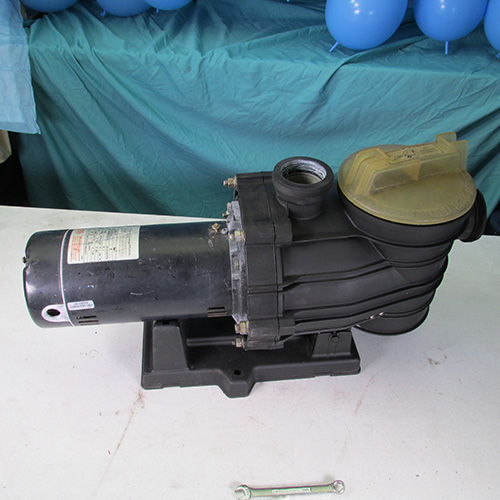
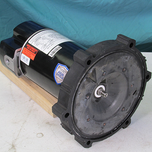
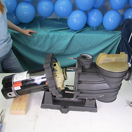
How To Change Motor & Seal
Sta-Rite Dyna-Glas & Maxi-Glas, Dyna-Pro
FloTec AT 251001 & AT 251501
These images are available in Hi-Def
Right Click & open in new tab for
closer inspection


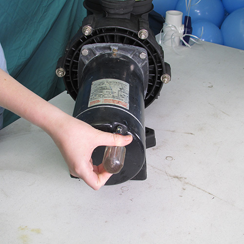
Step 1
The first thing we do is loosen the screws on the rear cover plate of the existing motor.
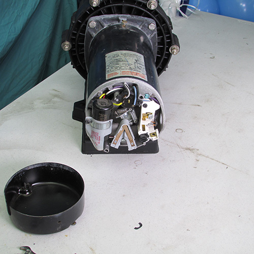
Step 2
Carefully remove the back cover plate by sliding it rear ward as shown. If it is stuck or stubborn you may have to tap it gently with a screwdriver or chisel at the seam.
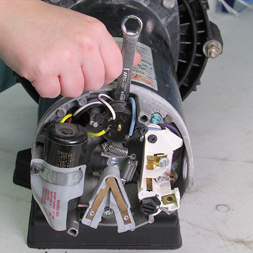
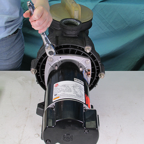
Step 3
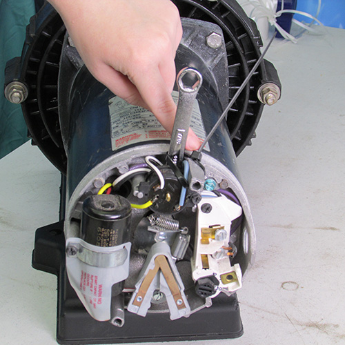
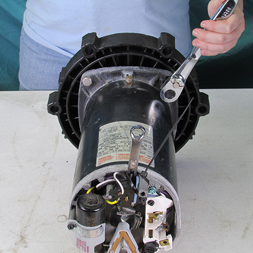
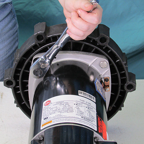
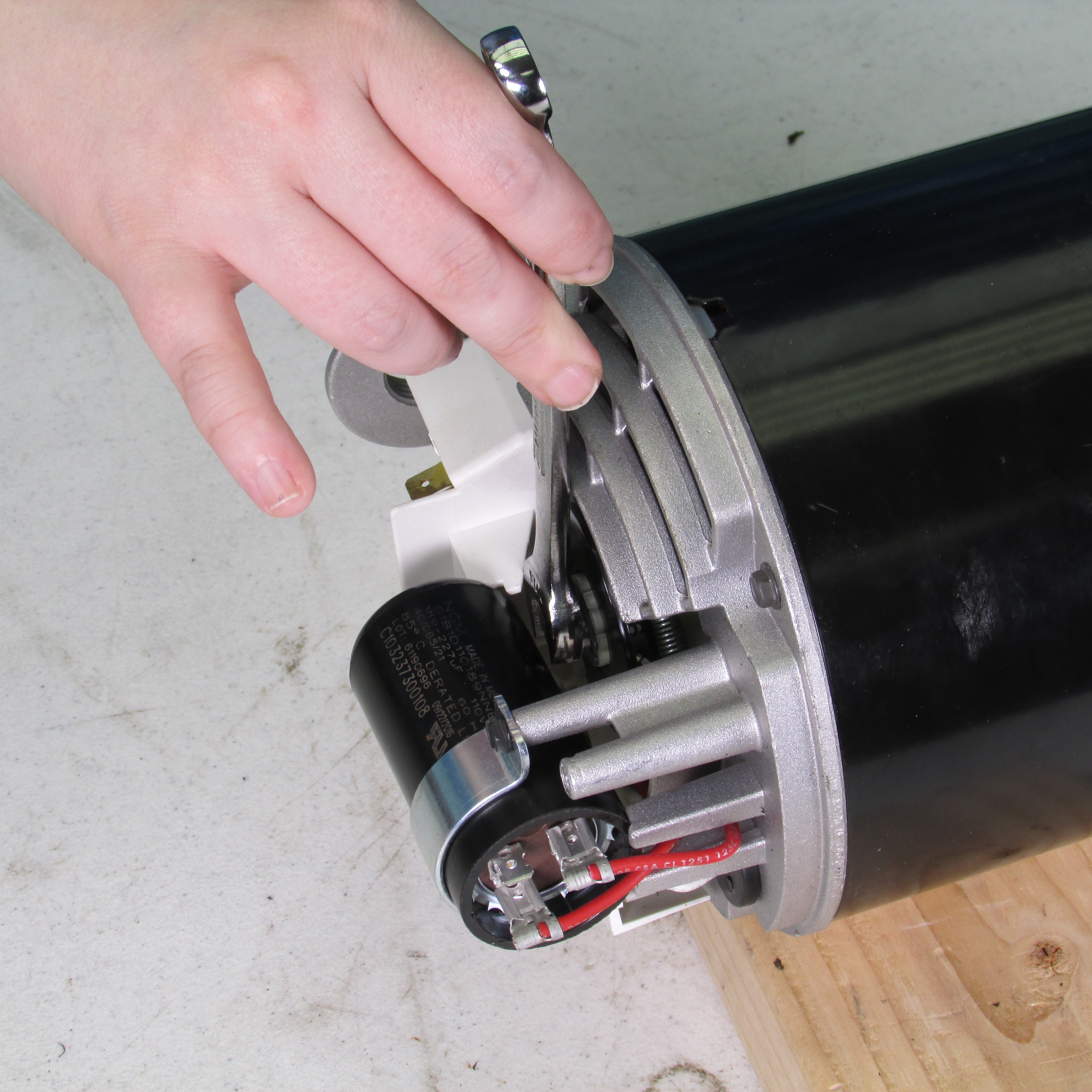
Insert a 7/16" open end wrench behind the overload switch as shown to lock the shaft from turning.
Step 4
Lock the open end wrench to the motor post with a zip tie as shown. This will prevent the wrench from falling out as we work on the motor and allow the shaft to remain locked.
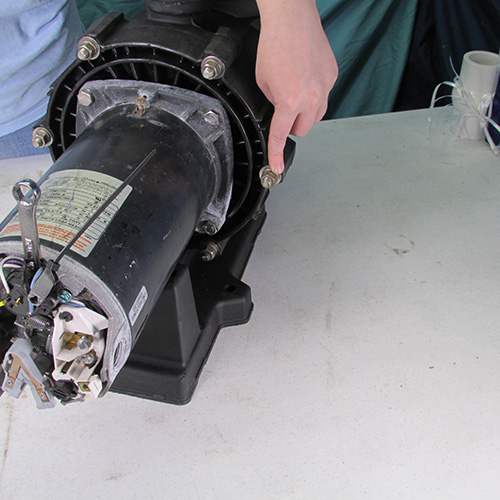
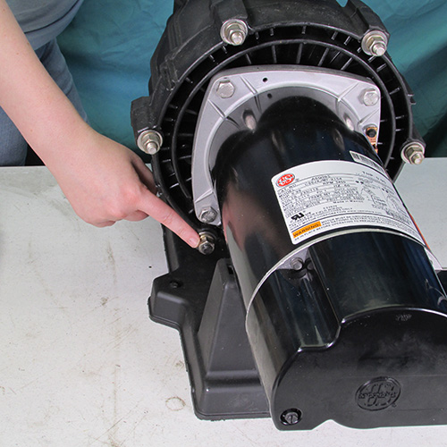
Step 5
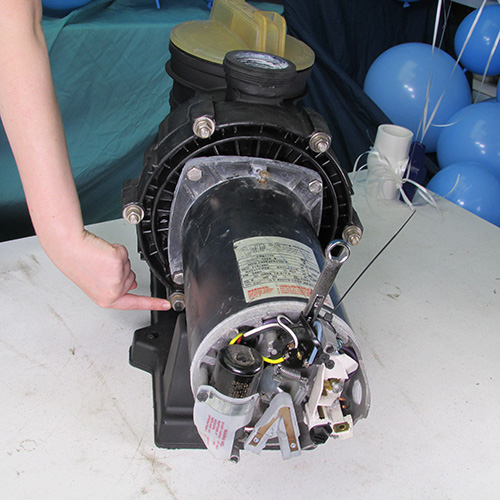
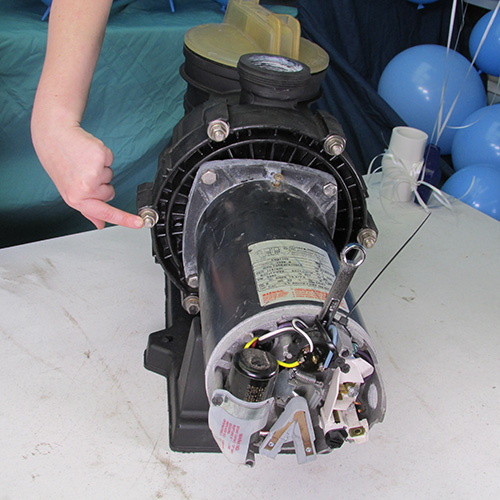
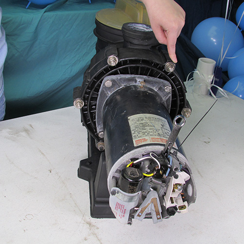
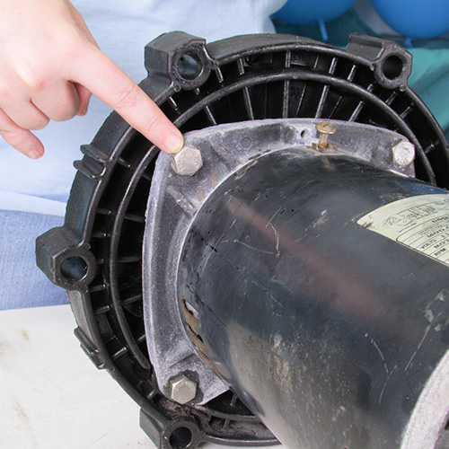
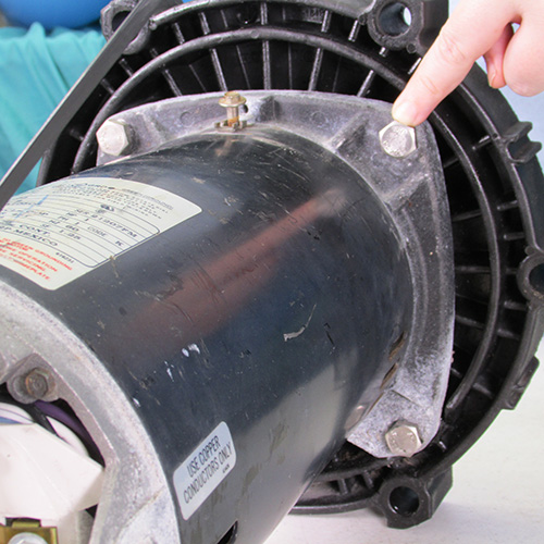
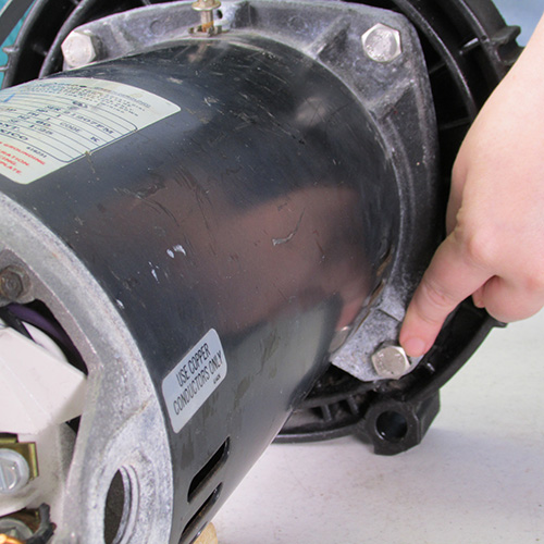
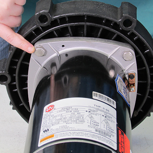
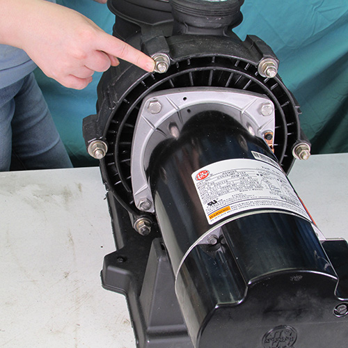
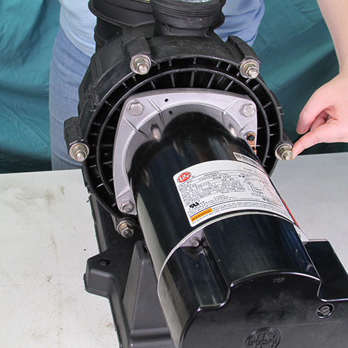
Next we will remove the six 9/16" nuts and washers as shown. These are located in a circular pattern at the edge of the seal plate. Do not remove the four bolts that attach the motor to the seal plate at this time. That is done at a later step.
Bolt 1
Bolt 2
Bolt 3
Bolt 4
Bolt 5
Bolt 6
DO NOT REMOVE THESE BOLTS AT THIS TIME
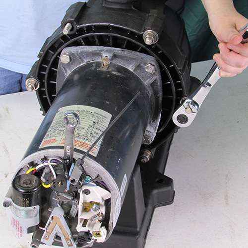
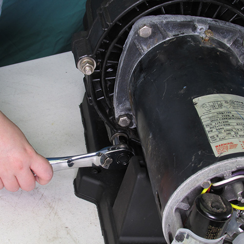
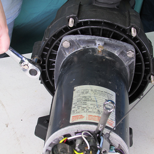
Use a 9/16" ratchet wrench to speed things up.
This is what the nuts and washers should look like after they are removed.
Step 6
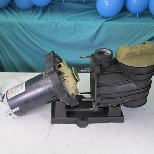
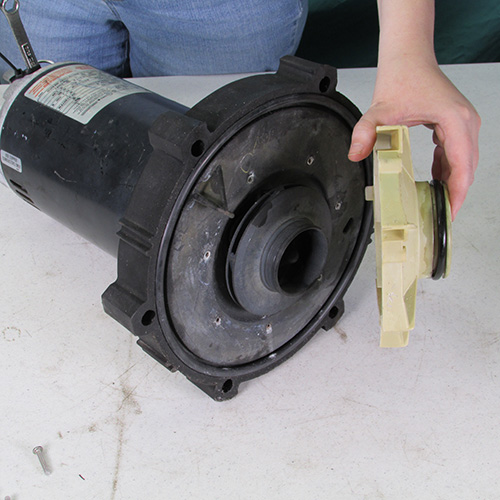
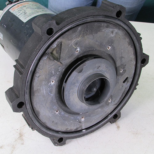
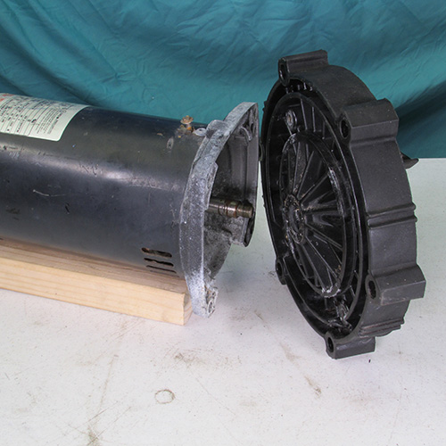
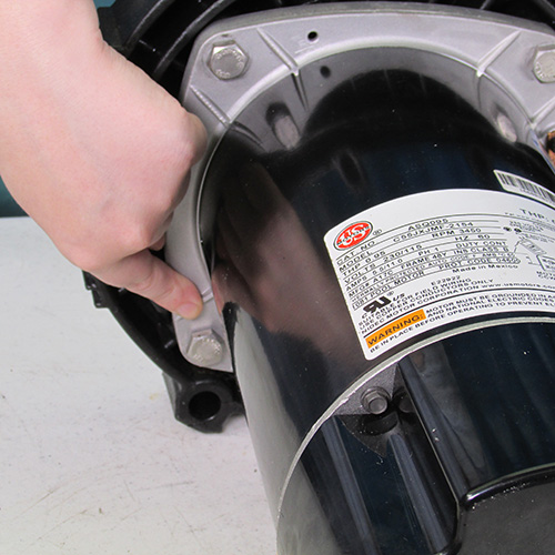
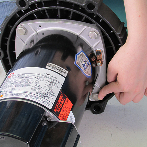
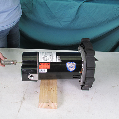
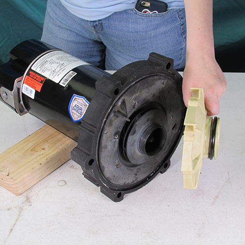
Separate the seal plate from the wet end assembly using two screw drivers. Pry gently and carefully at the seam as shown and pull back the power unit assembly containing the motor. For the purposes of this demo we have the wet end assembly on our work bench. In a real life scenario the front wet end assembly will remain connected to the homeowner's pool plumbing and remain in the yard on the pool equipment's slab.
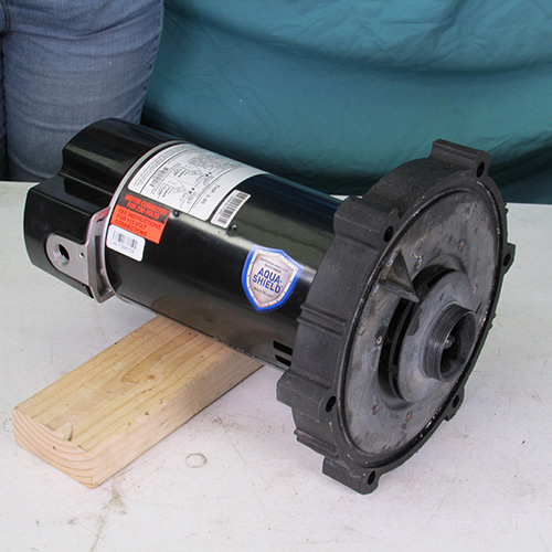
After you pry it out the power unit should just slide out as shown.
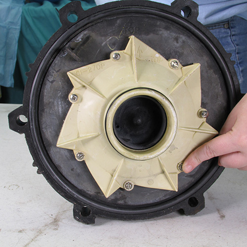
Step 7
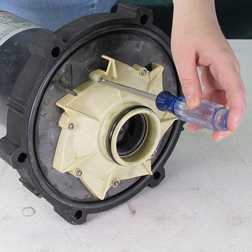
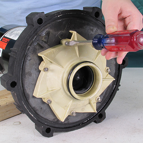
The next step is to remove the diffuser. We will accomplish this by removing the 7 diffuser screws as shown.
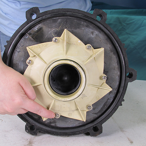
Step 8
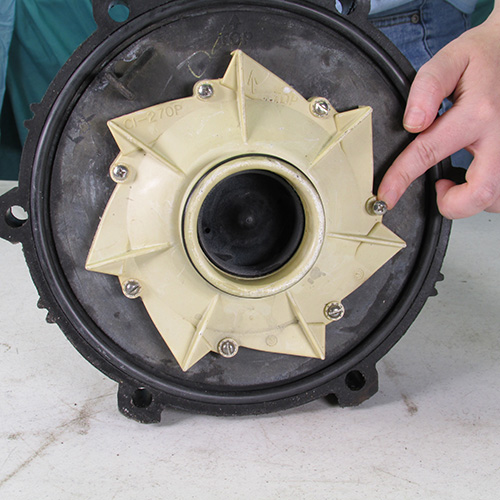
After removing the diffuser screws simply grasp the diffuser and pull it forward it should come off fairly easily. If it is stubborn you can pry it off gently with a small screwdriver but go slow and pry carefully.
Step 9
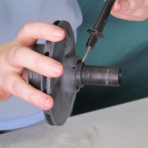
The next step is to remove the impeller. We accomplish this by turning the impeller counter clockwise sometimes you can just grab the impeller by hand preferably using a leather glove and rotating it counter clockwise. If the impeller is stuck you can try a large pair of channel lock pliers around the outer diameter of the impeller or a strap wrench. Do not twist the impeller or put tools on the impeller nose this will cause it to break apart.
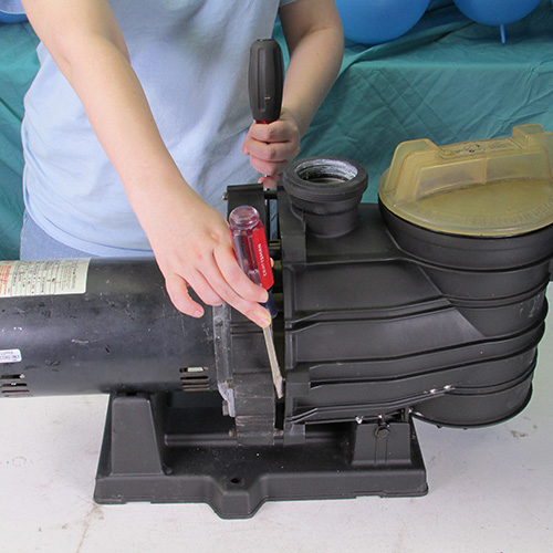
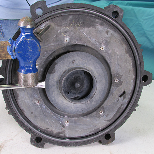
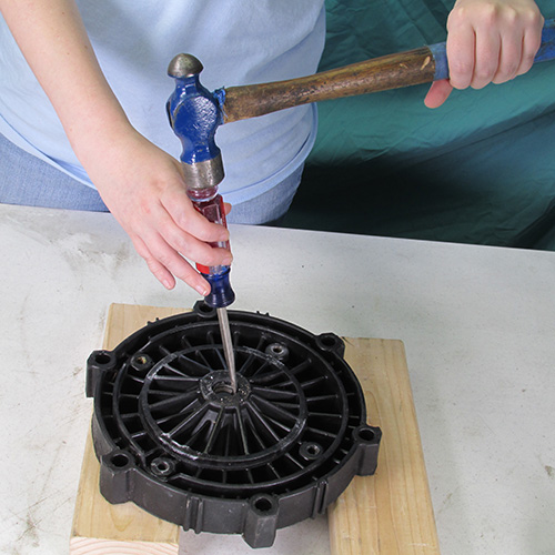
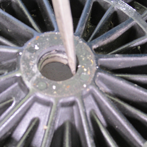
A method that we find very successful in removing impellers is to simply insert the blade of a large screwdriver into the edge of the impeller as shown and to strike it with a large hammer in the counter clockwise direction as shown. The resulting impact will usually free up the most stubborn impeller. Always use proper body and eye protection when using these type of tools.
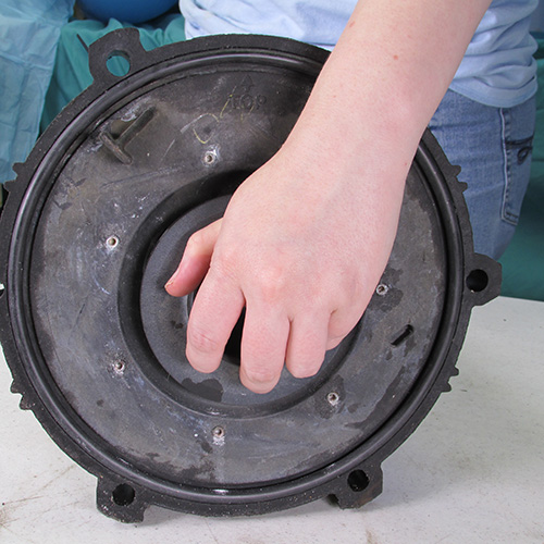
After the impeller is jarred loose we simply grasp it and rotate it in a counter clockwise direction to remove it.
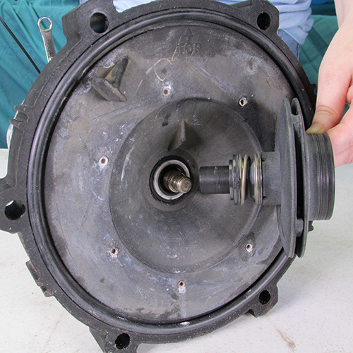
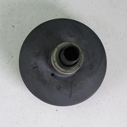
This is what it looks like when the impeller is removed.
Step 10
Remove the four 9/16" bolts holding the motor to the seal plate as shown.
A 9/16" ratchet wrench will help speed up this process.
Take the four bolts and set them aside for later.
Step 11
Remove the seal plate from the motor by pulling it forward as shown. If it is stuck you can tap it gently with a rubber mallet or a piece of wood. Do not use a metal hammer.
You can discard the old motor now if you are replacing it with a new one. If you are simply installing a new seal then save the old motor for reinstallation.
Step 12
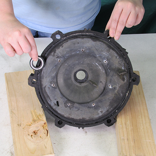
Using a screwdriver and a hammer gently tap the seal seat out of the seal plate as shown. Go slow and be careful because you do not want to damage the seal plate.
This image shows the seal seat removed from the seal plate.
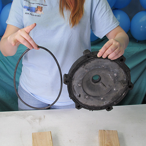
Remove the O-ring from the seal plate and set it aside.
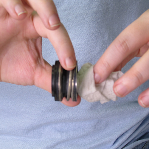
Step 13
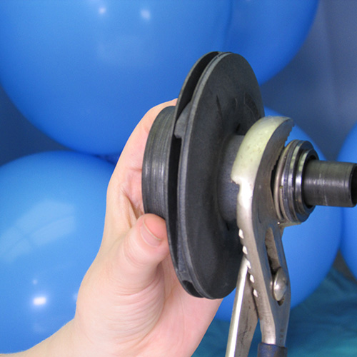
The next step is to remove the seal head from the impeller shaft. We do this by grasping the seal head with channel lock pliers and rotate in a twisting motion and at the same time pull the seal head off.
Many times the seal will break up into pieces when being removed it is very important to remove all parts of the seal. Note in this photo there is a small O-ring still remaining. This must be removed.
Step 14
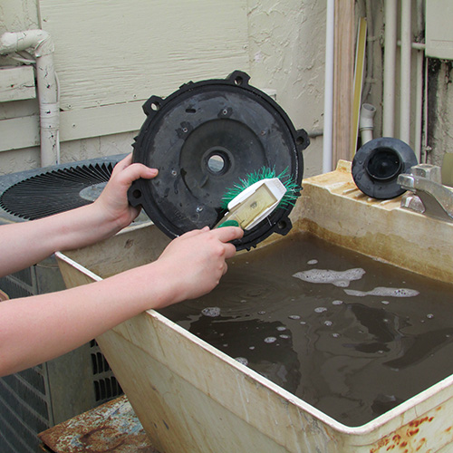
At this point we should wash the seal plate with soap and water.
Step 15
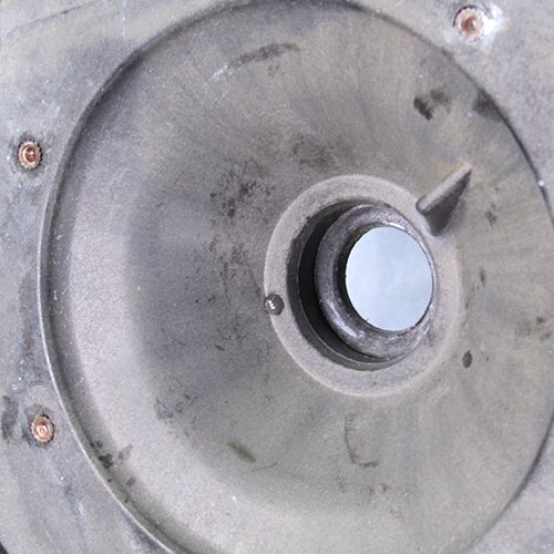
VERY IMPORTANT
Make a careful and thorough inspection of the seal plate assembly. Pay special attention to the center hole where the seal seat is installed. Check for any evidence of distortion caused by melting due to excessive heat. The surfaces should be smooth and clean. Do not use the seal plate if it is damaged. Using a damaged or melted seal plate will result in the seal leaking and cause the new motor to fail in a short period of time. The motor manufacturer will not warranty a new motor if it shows signs of water damage caused by seal failure.
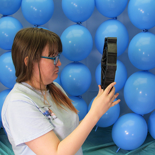
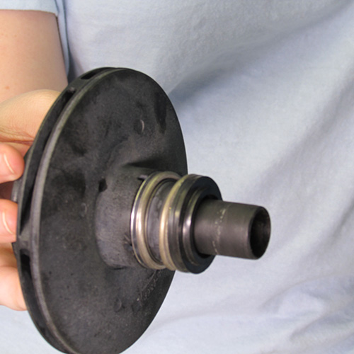
Step 16
Inspect the impeller for any damage especially look for cracks in the tail. That's the part that extends outward from the impeller disk. If there are any cracks in the impeller tail replace the impeller. Look very carefully because these cracks may be very small and difficult to see.
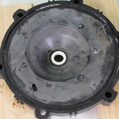
Inspect the seal plate bore.
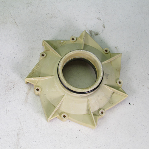
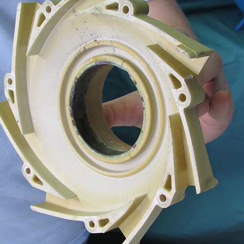
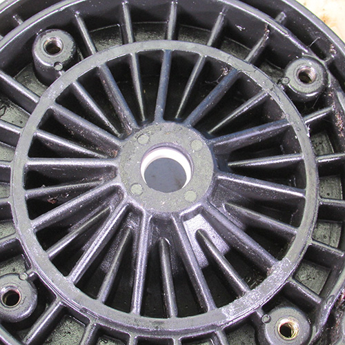
Inspect the diffuser look for cracks and wear around the bronze wear ring. If it looks very corroded it may be advised to replace the diffuser.
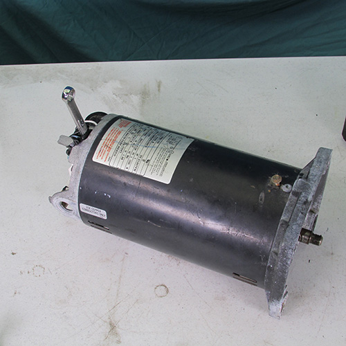
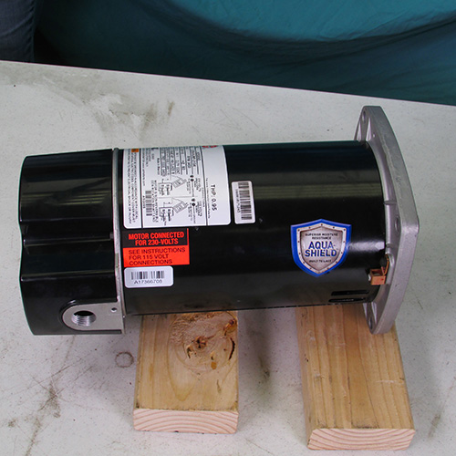
Step 17
Remove the new motor from the box and put it on two blocks as shown.
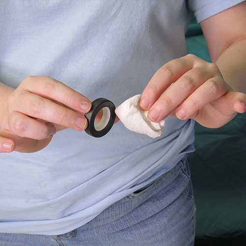
Step 18
Set the seal plate on a couple of blocks as shown in preparation of the installation of the seal seat.
Take the seal seat out of the box and lubricate it with soapy water or an approved rubber lubricant such as P80 or US seal lube. Do not use oil, grease, Magic Lube, WD40, or any petroleum product. Do not use silicone or Teflon either.
Step 19
Step 20
Place the seal seat assembly into the bore of the seal plate as shown.
Using the butt of a clean screwdriver carefully press the seal into place as shown.
Be sure that the seal seat is pressed in squarely and evenly and not cocked or crooked.
Inspect the backside too make sure the rubber ring is even around the entire periphery of the bore.
Do a final inspection if everything looks good we are ready for the final assembly.
Step 21
Set the seal plate on the front surface of the motor and attach the four bolts as shown.
Bolt 1
Bolt 2
Bolt 3
Bolt 4
Tighten the bolts gently with a 9/16" wrench.
Step 22
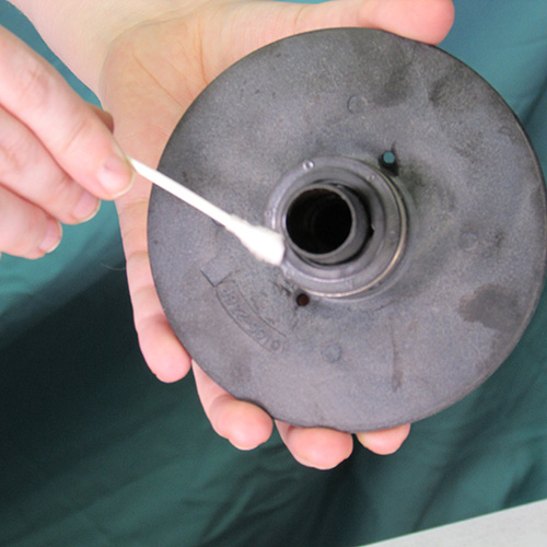
Using a cotton swab saturated with rubbing alcohol carefully clean the white portion of the seal seat assembly.
Step 23
Lubricate the bore of the seal head assembly with soapy water or P80 or US seal lube. Do not use oil, grease, WD40, Magic Lube, or any Teflon or silicone based product.
Step 24
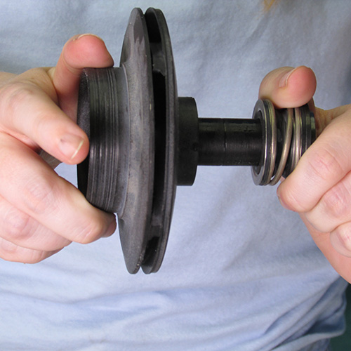
Slide the lubricated seal head assembly on to the impeller tail in a twisting motion as shown.
Step 25
Be sure the seal head assembly is butted up against the impeller as shown.
Step 26
Using a cotton swab saturated in alcohol clean the mating surface of the seal head assembly as shown.
Step 27
Carefully place the tail of the impeller assembly over the threaded portion of the shaft as shown and turn the impeller in a clockwise direction to tighten it to the shaft. Do this very carefully and slowly do not allow the seal ring surface to contact the metal shaft.
Turn the motor upside down and set it on a wood block as shown.
Tighten the impeller in a clockwise direction as shown hand tight is sufficient.
Step 28
Step 29
Remove the back cover from the motor as shown.
Step 30
Using a 7/16" wrench slide it on the rear end of the shaft to lock it.
Step 31
While holding the 7/16" wrench in one hand use your other hand to tighten the impeller in a clockwise direction. Hand tight should be sufficient.
Step 32
Turn the motor right side up and then replace the rear cover.
Step 33
Replace the diffuser on top of the impeller as shown.
Step 34
Tighten the diffuser screws.
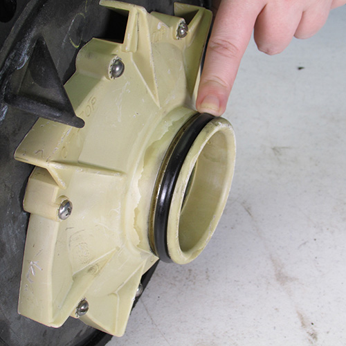
Notice the orientation of the diffuser it has the word "top" this should be in the top position as shown.
Step 35
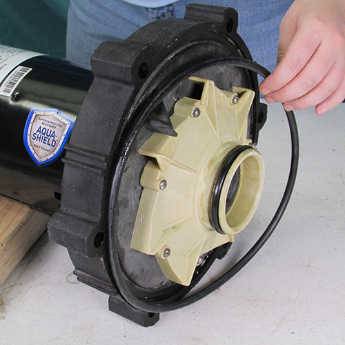
Replace the diffuser and body O-rings these you can lubricate with Magic Lube.
Step 36
Place the power unit next to the wet end assembly as shown.
Slide the power unit assembly on to the six studs protruding from the wet end assembly as shown.
Step 37
Install the six nuts in a staggered pattern as shown. There should be a flat washer a lock washer and then a nut in that order installed on each stud. Tighten the nuts with a 9/16" wrench. Use a criss cross pattern when tightening the nuts.
Step 39
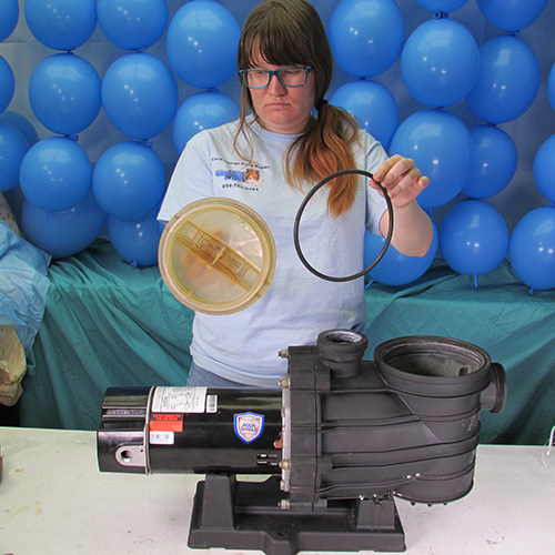
Install a new O-ring on the basket lid.
Step 40
Always fill the pump with water before running it. One or two gallons should be sufficient.
These instructions apply to these model numbers: MPE6C-204L, MPE6D-205L, MPE6E-206L, MPE6F-207L, MPE6G-208L, MPEA6D-204L, MPEA6E-205L, MPEA6F-206L, MPEA6G-207L, MPEAA6G-208L, MPRA6D-204L, MPRA6E-205L, MPRA6F-206L, MPRA6G-207L, MPRA6D-146L, MPRA6D-146LC, MPRA6E-147L, MPRA6E-147LC, MPRA6F-148L, MPRA6F-148LC, MPRA6G-155L, MPR6G-155LC, MPEA6D-146L, MPEA6E-147L, MPEA6F-148L, MPEA6G-155L, MPEAA6G-168L, MPFA6D-176L, MPFA6E-146L, MPFA6F-147L, MPRA6YF-174L, MPRA6YF-174LS, MPEA6YG-175L, MPEA6YG-175LS, MPEAA6YG-168L, MPEAA6YG-168LS