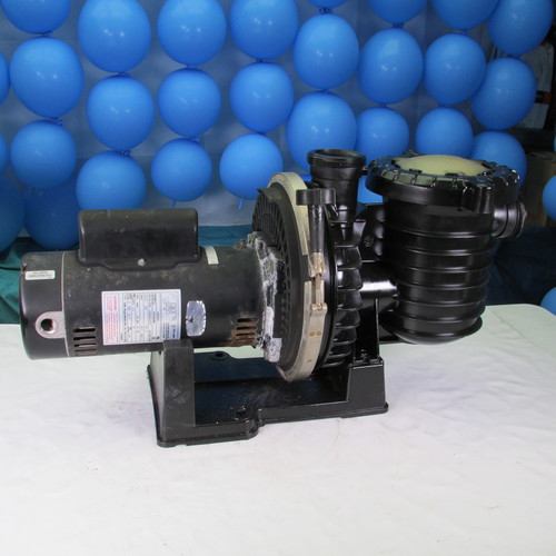
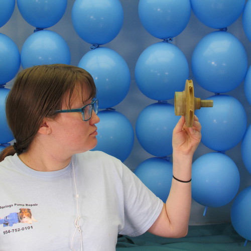
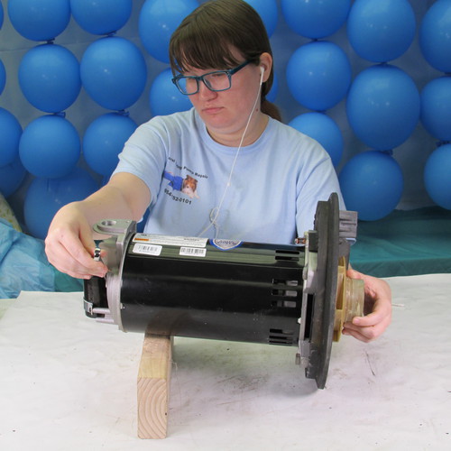
How to change the motor & seal
Sta-Rite Duraglas2 & Durapro Pool Pump
This instruction set covers both the:
Sta-Rite Duraglas 2
&
Sta-Rite Dura-Pro
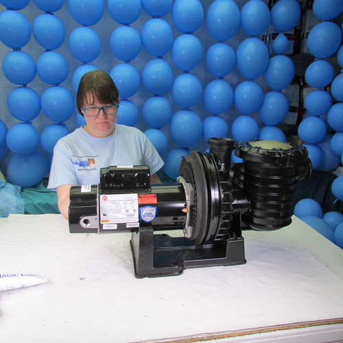
Both models share the same power unit
Only the wet end is different
Step by Step Instructions
Step 1
Using a one quarter inch nut driver we remove the two screws holding on the back cover of the motor.
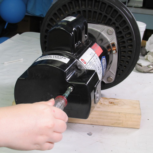
Step 2
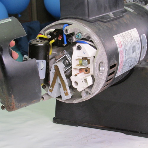
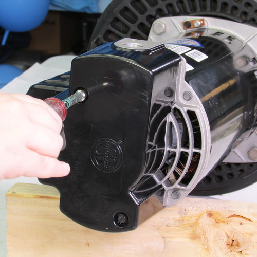
Gently remove the cover by prying the cover rearward. If it is stuck insert a screwdriver in the seam as shown and gently tap it rearward.
Step 3
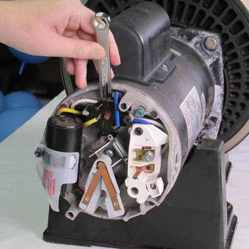
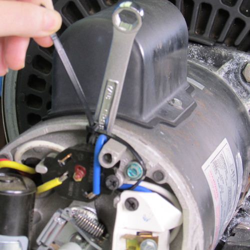
Insert a 7/16" open end wrench behind the overload protector and lock it on to the shaft behind the rotating govenor as shown.
Step 4
Next we will attach a tie strap to the wrench and secure it to the motor and endbell post as shown. This will prevent the wrench from falling out.
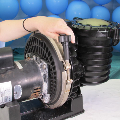
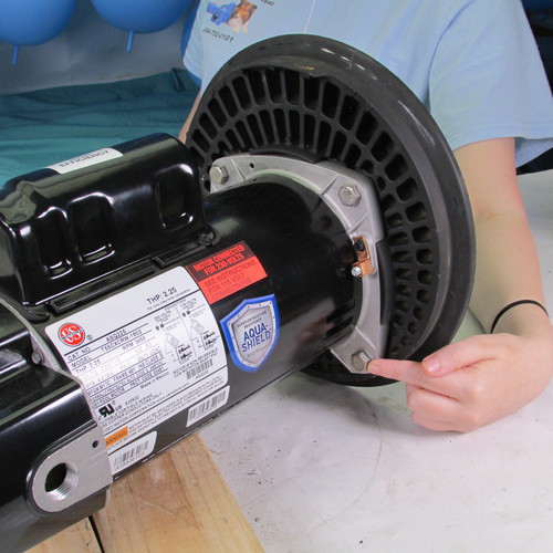
Next we loosen the locking band knob by twisting it in a counter clockwise direction. Some older pumps may not have a knob however they will have a 7/16" nut in which case use a 7/16" wrench or deep socket to remove the nut.
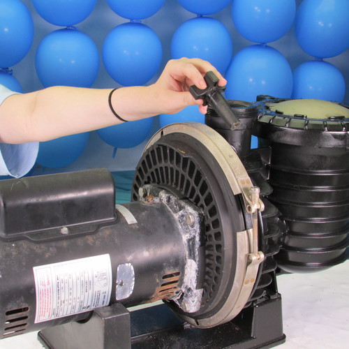
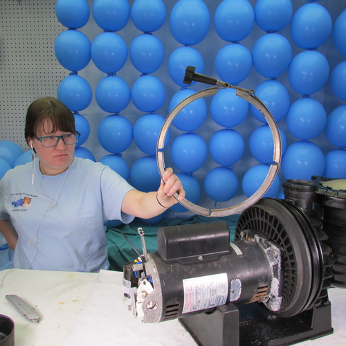
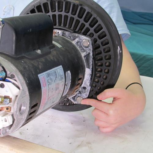
Step 5
Once the knob or nut is removed we will remove the locking band as shown by prying it off as shown.
Step 6
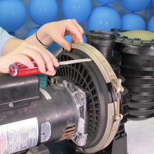
Set the band aside for reinstalltion later.
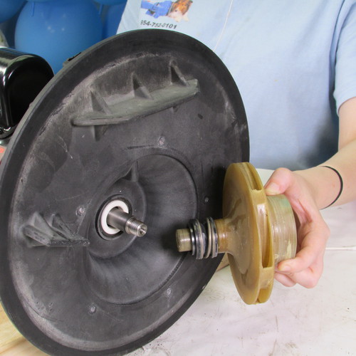
Using a couple of screwdrivers seprate the real power unit assembly containing the motor and impeller from the front wet end assembly by prying rearward as shown.
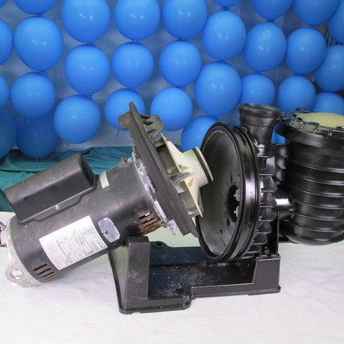
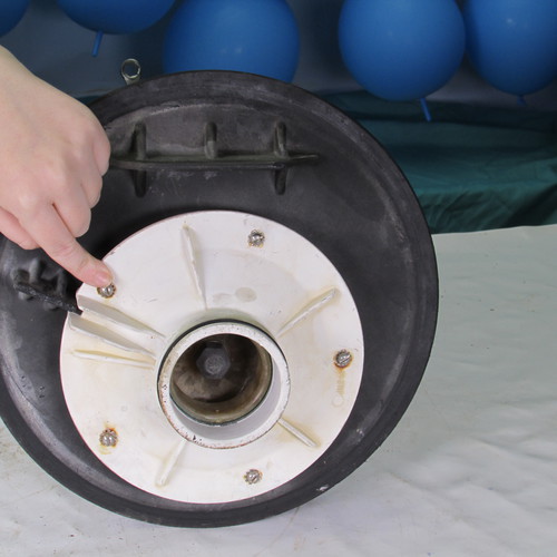
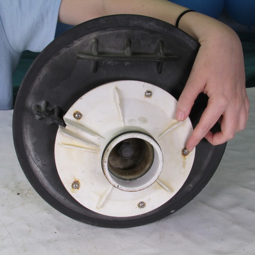
Step 7
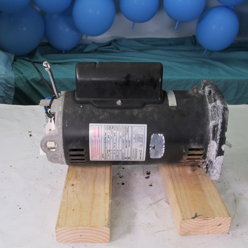
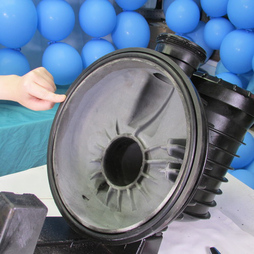
This is what it will look like when the power unit is removed. For the purpose of this demonstation we have removed the wet end assembly and brought it to the work bench. In a real life situation the wet end assembly will usuallly remain attached to the pool plumbing and stay on the pool equipment slab in the pool owners yard.
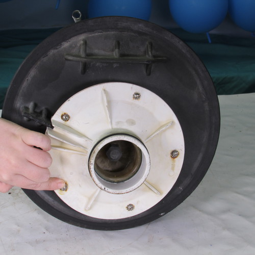
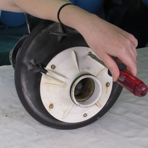
Next we remove the five diffusure screws by turning in a counter clockwise direction as shown.
Screw 1
Screw 2
Screw 3
Screw 4
Screw 5
Use the appropriate tool to remove the screws some pumps may use a flat bladed screwdriver head others may use a one quarter inch hex head or some may even have a number 2 philips. Some have star washers under the screw heads and some do not.
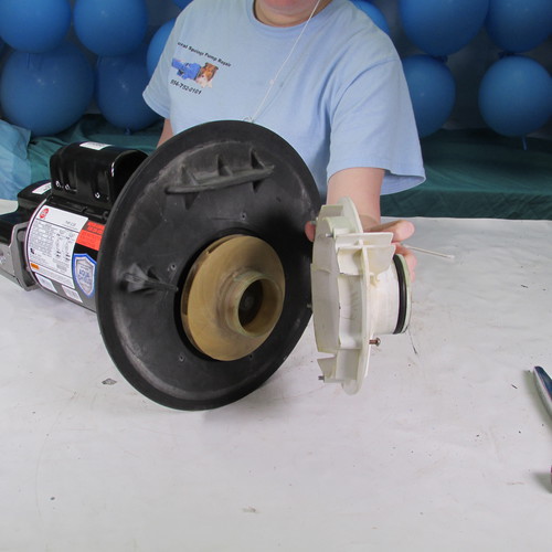
Step 8
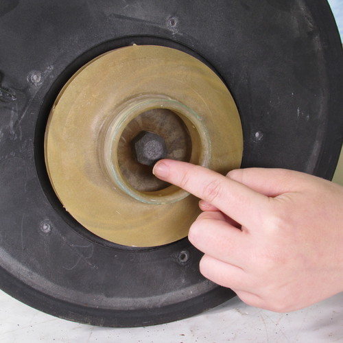
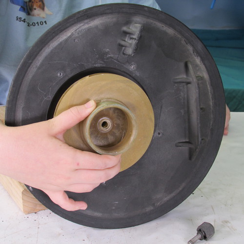
Remove the diffuser by pulling it away from the seal plate as shown.
Step 9
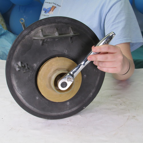
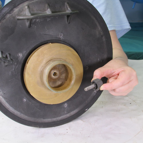
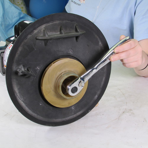
Next we remove the impeller locking screw. On this pump we have an 11/16 inch hex nut. Some pumps have a smaller nut and some have a philips head screw. It is important to note that this screw is a left hand thread. That means to remove it you must turn it to the right or in a clockwise direction.
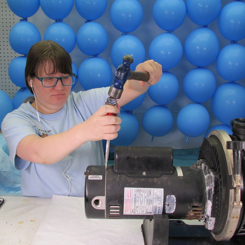
Step 10
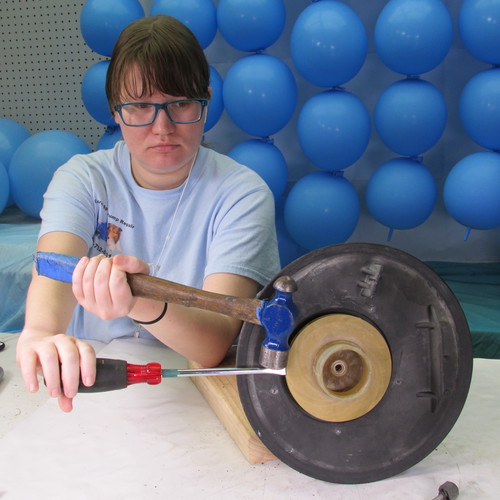
Next we must remove the impeller, this is done by twisting it in a counter clockwise or left direction. Sometimes the impeller can be removed by using a strap wrench on the outer large diameter, or using very large channel lock pliers on the large diameter. Do not put any tools on the small nose of the impeller as it will likely crack or break off. A method that we have found very successful in removing impellers is to insert a large flat bladed screwdriver into the outer edge of the impeller and strike the screwdriver shaft close to the impeller with a hammer. The resulting impact force will usually free up the most stubborn impellers. Then we simply twist off the impeller in a counter clockwise or left direction. Always use proper body and eye protection when using these tools.
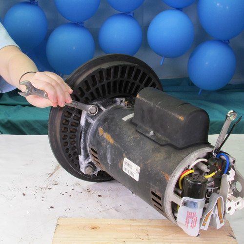
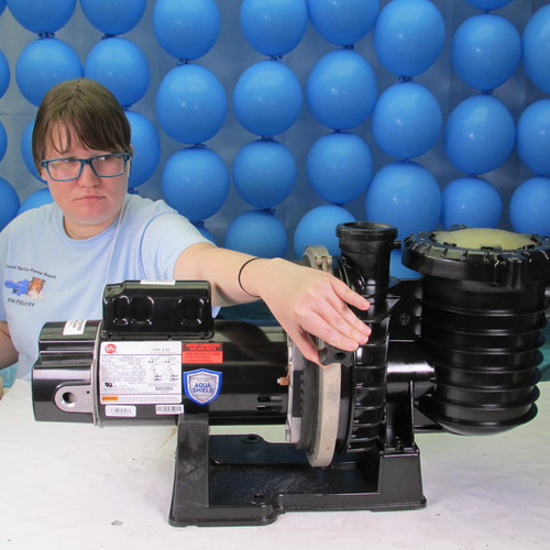
Step 11
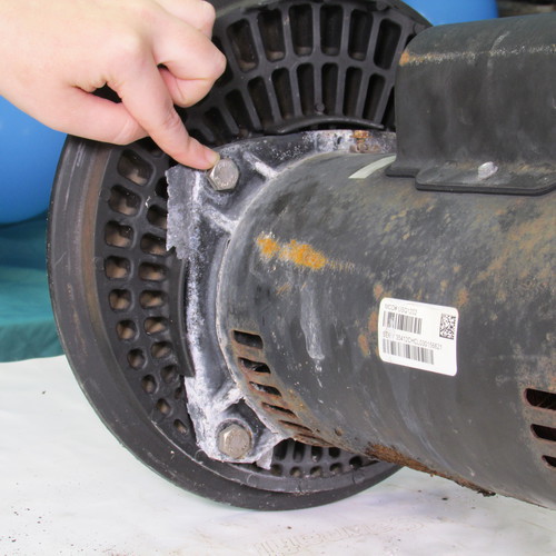
The next step will be to remove the four 9/16" bolts that attach the seal plate to the motor.
Bolt 1
Bolt 2
Bolt 3
Bolt 4
Remove these bolts with a 9/16" wrench sometimes the bolts are stubborn and you may have to tap the wrench with a hammer or mallet. Be careful and go slow. Sometimes an air or electric impact wrench can make the job easier.
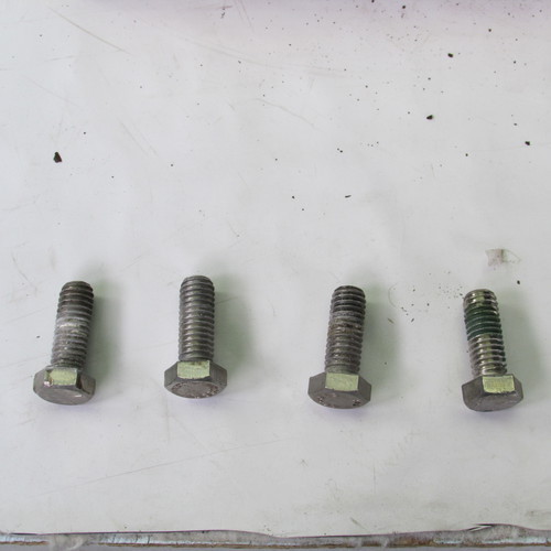
These are the four bolts after they are removed, they are usually stainless steel.
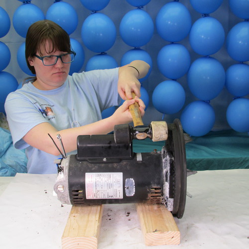
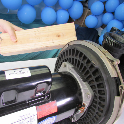
Step 12
After the four bolts are removed the next step is to gently tap the seal plate away from the motor using a soft mallet or a block of wood if a mallet is not available. Do not use a metal hammer under any circumstatnces.
Step 13
Depending on the year of manufacture, this model of pump may have two different seal plates. One type of seal plate will contain a copper cup or heat sink as shown on the left. The other type of seal plate does not have the copper cup. Both use the same seal and are interchangeable. The seal plate with the copper cup is no longer being made so if you have to replace it you will have to replace it with a newer one that no longer has the copper cup.
Step 15
At this point you can discard the old motor however if you are only doing a seal replacement then put the motor aside for reinstallation later.
Step 16
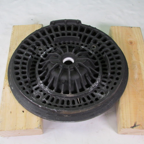
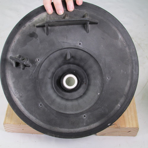
Place the seal plate assembly on a couple of 2x4s with the backside up.
Step 17
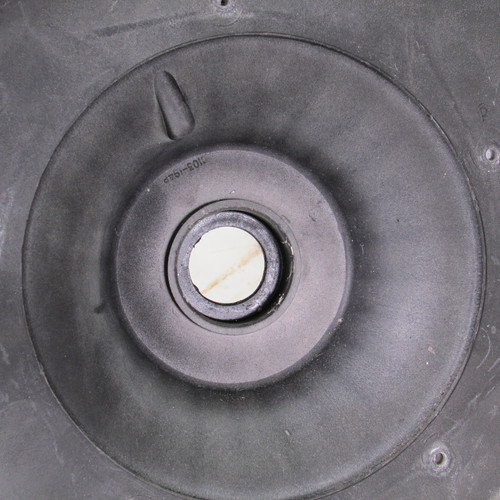
Using a flat bladed screwdriver that is inserted against the rear of the seal seat assembly as shown gently tap the seal seat assembly away from the seal plate.
Step 18
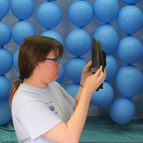
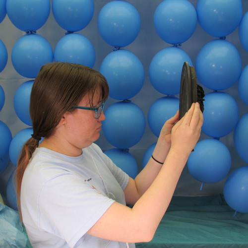
Carefully inspect the seal plate assembly pay particular attention to the area surrounding the seal seat bore. Be sure there is no evidence of deformation caused by melting or heat damage. Do not use a seal plate that shows any evidence of heat damage.
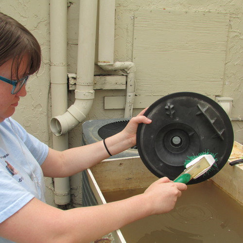
Step 19
If the seal plate looks good after your inspection the next step is to clean it with soap and water to prepare it for reassembly.
Step 20
In this step we take the seal assembly of the new seal and lurbicate it with a soap and water solution. Do not use grease, oil, WD40, Magic Lube, silicone, teflon, or any petroleum based product. A rubber lubricant such as P80 or US Seal lube is ok however most pool owners do not have this readily available therefore soap and water is a good and safe substitute.
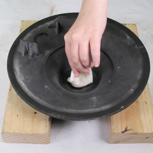
Step 21
Lurbicate the bore of the seal plate.
Step 22
Place the seal seat into the bore of the seal plate as shown.
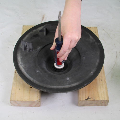
Step 23
Using the rounded butt of a screwdriver carefully press the seal seat into the seal plate as shown.
Step 24
Inspect the seal and make sure that it is seated properly. Make sure it is not crooked or cocked.
Step 25
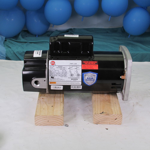
Unbox the new motor and place it on a couple of 2x4s and if you're only replacing the seal then recover the old motor that you set aside previously and place it on the bench in preperation for reinstallation.
Step 26
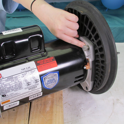
Place the seal plate assembly up against the front flange as shown. Be careful that the motor shaft does not make contact with the seal seat assembly that you just installed.
Step 27
Next we will insert the four bolts that hold the motor to the seal plate.
Bolt 1
Bolt 2
Bolt 3
Bolt 4
Next we will tighten the four 9/16" bolts with a wrench. Tighten them up gently and firmly but do not over tighten.
Step 28
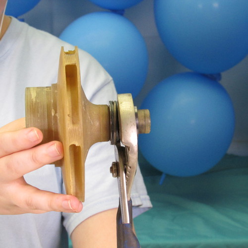
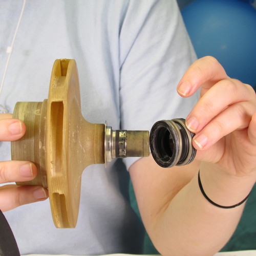
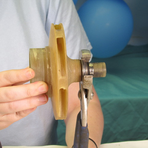
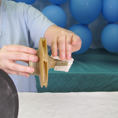
Next we will remove the old seal head assembly from the impeller we do this by grasping the seal head assembly with channel lock pliers and twisting the seal off.
It is important to remove all parts of the seal sometimes, actually many times, in this process the seal breaks apart.
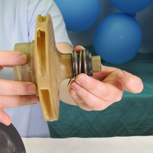
It is very important to remove this rubber ring too sometimes people leave inadvertantly leave the ring on.
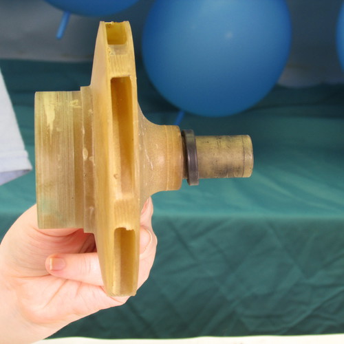
This is what the impeller tail should look like when the seal head is removed there should be nothing on the impeller tail.
Step 29
Using soap water and a degreasing detergent such as tide or dawn, carefully and thoroughly clean the tail of the impeller. There should be no grease, oil, or Magic Lube on this part. If somebody put it on previously, get rid of it. There has to be a friction fit between the impeller tail and seal head bore
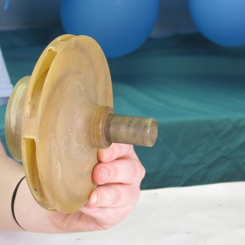
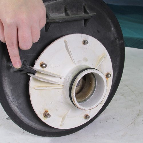
Step 30
Carefully do a thorough inspection of the impeller be sure there is no debris in the vanes. If there is any debris in the vanes use a stiff wire such as a coat hanger to clear the impeller.
Step 31
Lubricate the impeller tail with soap and water. Do not use grease, oil, WD40, Magic Lube, teflon, or silicone. An approved rubber lubricant such as P80 or US Seal lube is ok but most homeowners do not have these so soap and water is an acceptable substitute and will not cause damage to the seal.
Step 32
Lubricate the seal head assembly with soap and water. Do not use grease, oil, WD40, Magic Lube, teflon, or silicone. An approved rubber lubricant such as P80 or US Seal lube is ok but most homeowners do not have these so soap and water is an acceptable substitute and will not cause damage to the seal.
Step 33
Carefully install the seal head on to the impeller by twisting it on. Twist and press at the same time so it butts up to the back of the impeller as shown. Do not use any metal tools as this will most likely damage the delicate seal head.
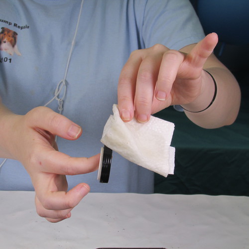
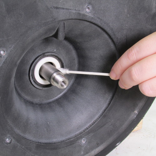
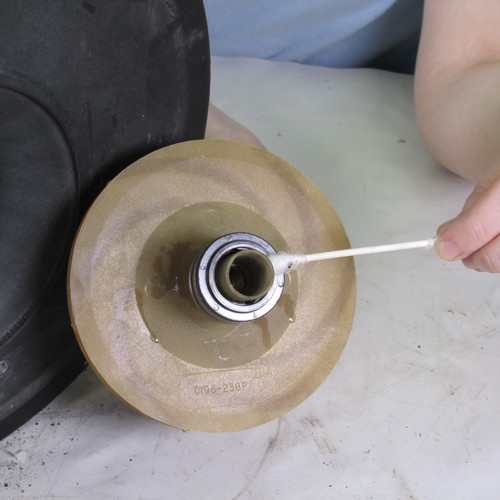
Step 34
Using a cotton swap saturated in rubbing alcohol carefully clean the seal seat assembly as shown. Do not omitt this step in the interest of time as this is very important. The seal surfaces need to be clean or it will result in a shorter life of the seal.
Using a cotton swap saturated in rubbing alcohol carefully clean the seal head assembly as shown. Do not omitt this step in the interest of time as this is very important. The seal surfaces need to be clean or it will result in a shorter life of the seal.
Step 35
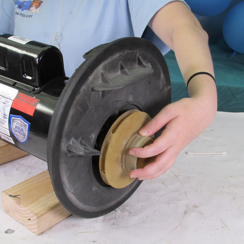
Step 36
Next we install the impeller by putting it on the shaft and twisting it in a clockwise direction as shown.
Step 37
Next we remove the rear cover of the motor in preperation of locking the shaft.
Step 38
Insert a 7/16" open end wrench on to the flats on the rear of the motor and hold it there with one hand use your other hand to tighten the impeller in a clockwise direction. Hand tight is sufficient.
Step 39
Reinstall the rear cover that was removed previously.
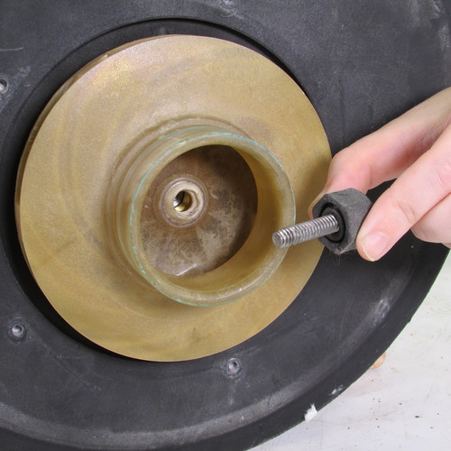
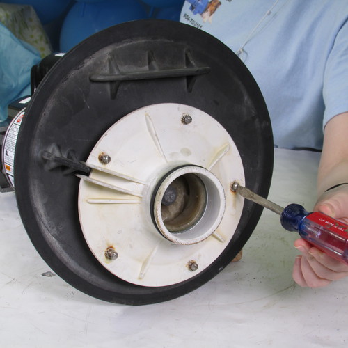
Step 40
VERY IMPORTANT
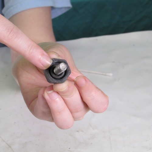
Next we will install the impeller locking screw. It is very important to be sure that the rubber O-ring is installed and is in good condition and not damaged. If you do not have the O-ring or it is rotten or broken do not proceed. If the ring is broken or missing it will cause the pump to have a tiny leak that will eventually get into the front bearing of the new motor and destroy it. Most likely the motor manufacturer will not honor a warranty claim because they will say the motor was water damaged. Water damage is excluded by most motor manufacturers and is the number one cause for warranty denials. That little oring can be the difference between a pump that lasts only a year or two or one that goes for many many years. The leak may be so small that you may not notice it, but it will ruin the motor
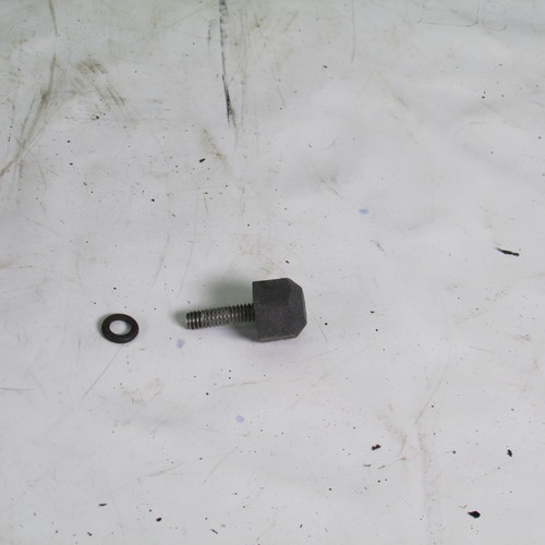
Here are the details of the screw and the little O-ring.
If all looks well then we can reinstall the impeller locking screw. Remember that this screw is a left hand or reverse thread screw that means to tighten it you must turn it in a counter clockwise or left direction.
Step 41
Next we reinstall the diffuser.
Notice that the slot in the diffuser slides into the key on the seal plate as shown.
Tighten the 5 diffuser screws as shown.
Step 42
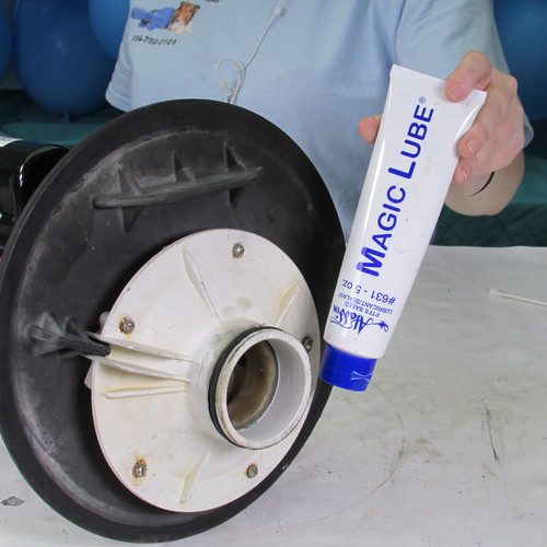
Next we will install a new O-ring on the diffuser nose. It is acceptable to use Magic Lube to lubricate these O-rings.
Step 43
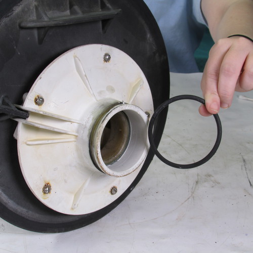
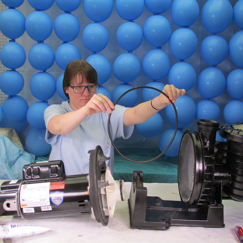
In this step we will install a new body O-ring.
This is done by installing it into the channel of the wet end assembly as shown. If you lubricate it with Magic Lube it will stick in place.
Next place the power unit into the wet end assembly as shown and press into place.
Step 44
Step 45
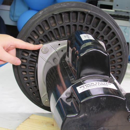
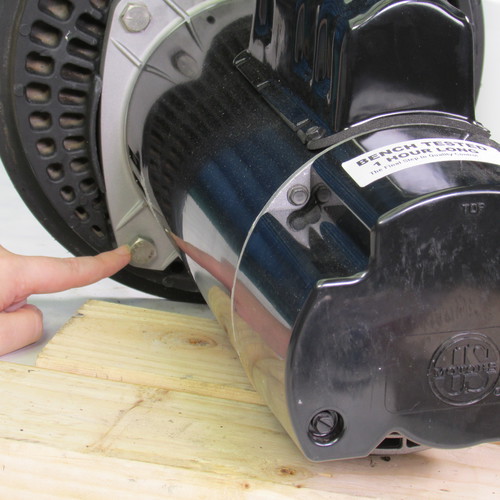
Slide the stainless steel locking band over the seal plate as shown and attempt to put on the knob if it does not go on you may need to gently tap the locking band inward as shown. Use a rubber mallet or a piece of wood do not use a metal hammer.
Step 46
The next step is to tighten the locking knob or the 7/16" nut if that is what your pump had.
Step 47
Replace the lid O-ring you can lubricate this with Magic Lube too.
Step 48
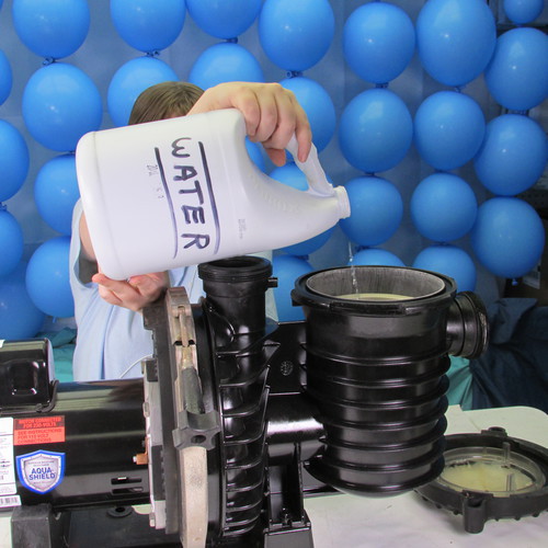
Be sure to fill the pump with water before running it one to two gallons should be sufficient.
How to replace motor & seal on the following Sta Rite & Pentair Pumps
P4R6CL, P4RA6CL, P4EA6CL, P4R6DL, P4R6EL, P4RA6DL, P4RA6EL, P4RA6FL, P4RA6GL, P4EA6DL, P4EA6EL, P4EA6FL, P4EA6GL, DURA 2, MAXI PRO, P6E6F-207L, P6E6E-206L, P6RGE-206L, P6RA6G-207L, P6R6D-205L, P6EA6E-205L, P6RA6E-205L, P6E6G-208L, P6EA6F-206L, P6E6D-205L, 345078, PHK2E6D, P6E6C-204L, P6RA6YF-206L, P6EAA6G-208L, P6RA6Y6-207L, P6RAA6F-216L, P6R6H-209L, P6R62F3-188, P6EAA6F-216L, P6EA636-205, P6R6263-189