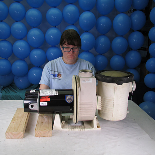
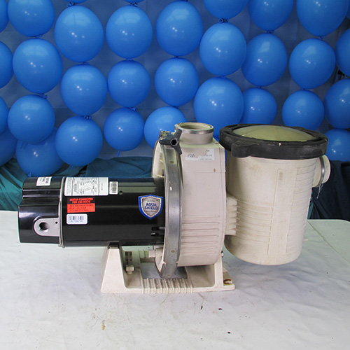
How To Change The Motor on Ultra-Flo Pump
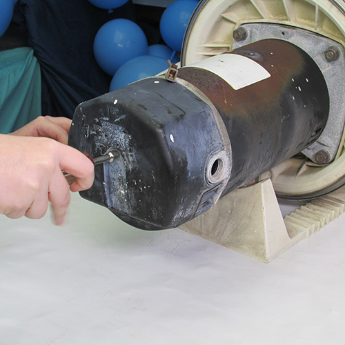
Step 1
The first thing we do is remove the back cover. In this case we remove one screw in the center of the rear cover. We then remove the rear cover pulling it off.
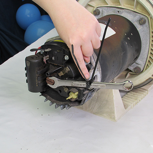
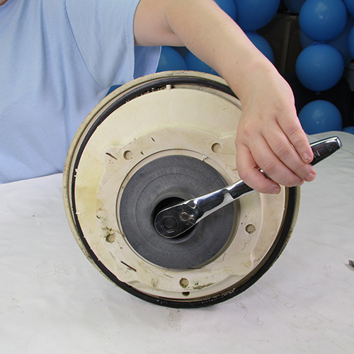
Step 2
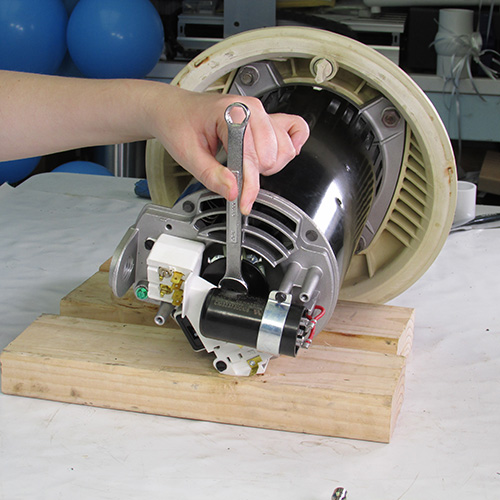
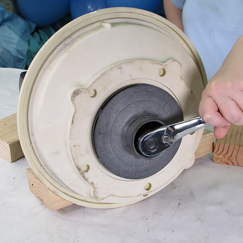
We insert a half inch wrench on the shaft of the motor and lock it with a zip tie. This will keep the motor shaft from turning. The zip tie will keep the wrench from falling off.
Other brand motors may use different methods of holding the shaft, but the principle is the same, keep the shaft from turning.
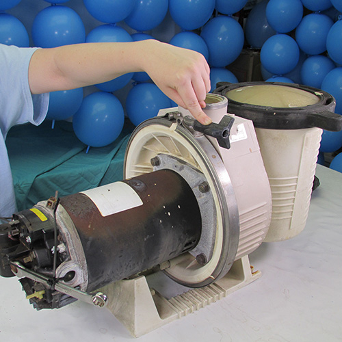
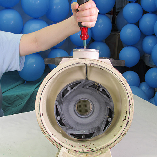
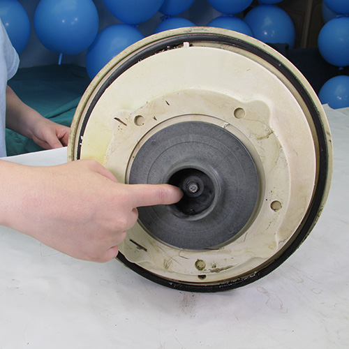
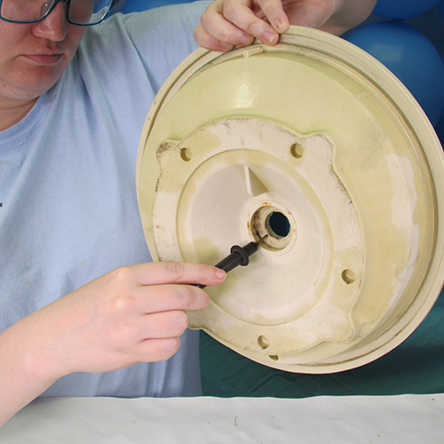
Step 3
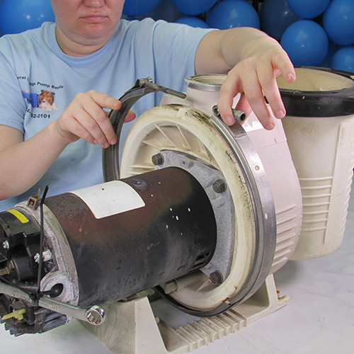
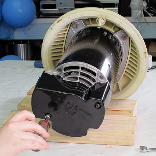
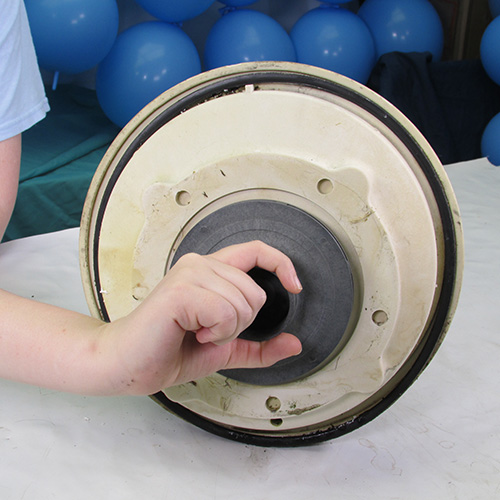
We remove the locking knob by twisting it in a counter clockwise direction.
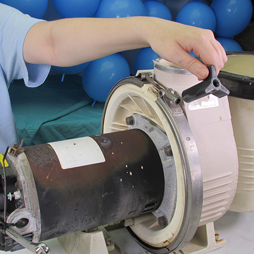
Step 4
Once the knob is removed we slide off the stainless steel locking band. Usually it will slide right off but if it is stuck it can be pried loose with a couple of screwdrivers.
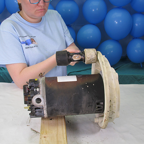
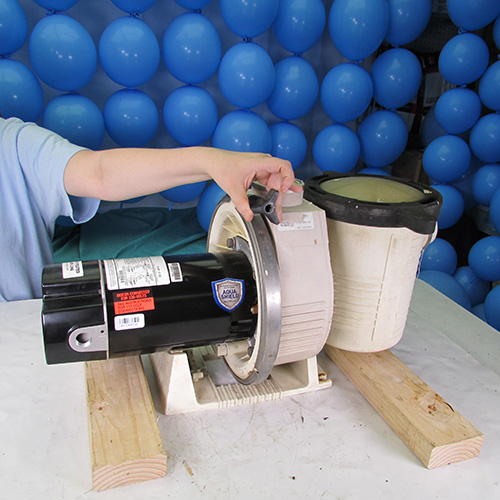
Step 5
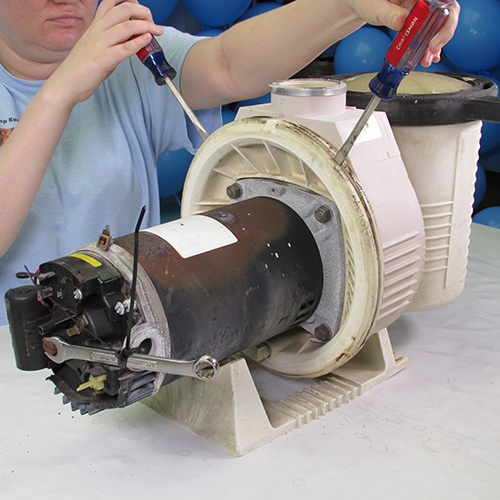
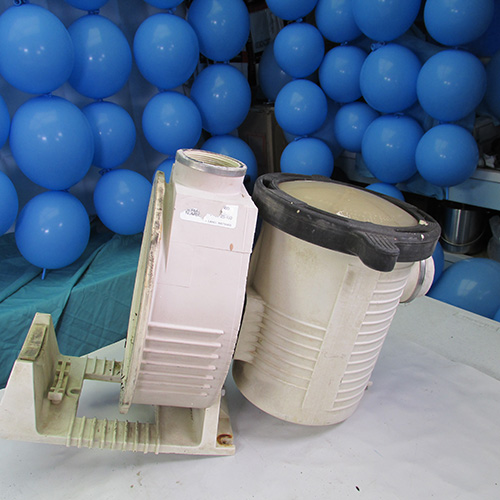
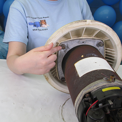
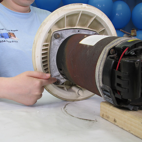
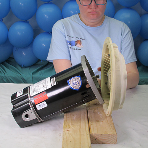
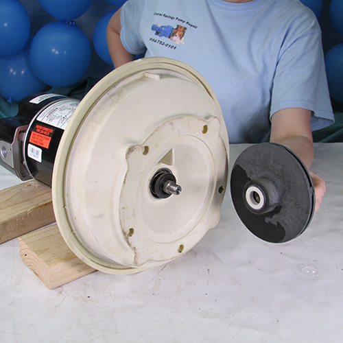
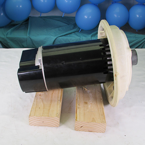
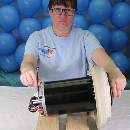
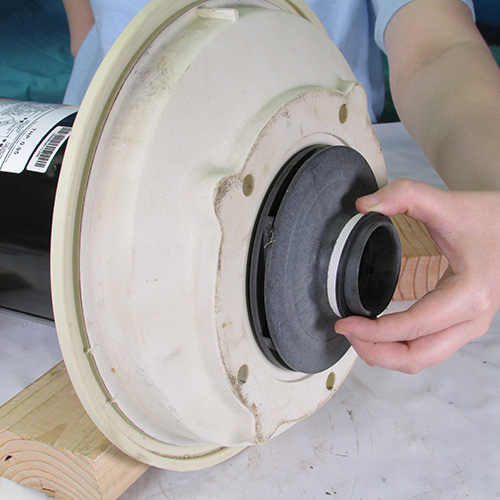
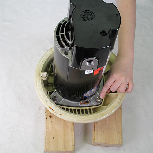
Next we separate the motor and power unit from the wet end housing by prying it loose at the crack with two screwdrivers as shown. Work the screwdrivers around the peripherary of the seal plate.
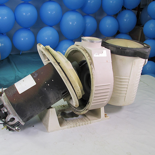
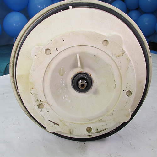
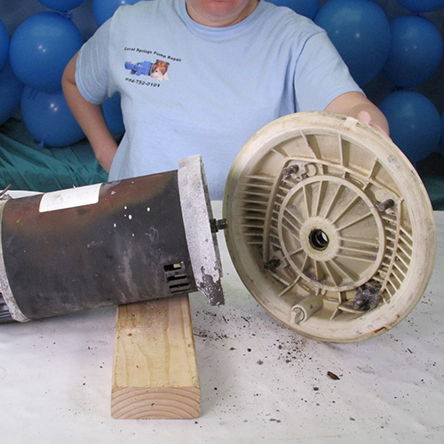
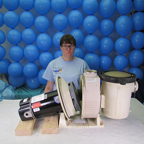
This is what it looks like when the power unit is separated from the wet end. For this demonstration we have removed the wet end or tank body and placed it on the work bench. In a real life scenario the wet end will usually be attached to the pool plumbing and remain on the equipment pad in the pool owner's yard.
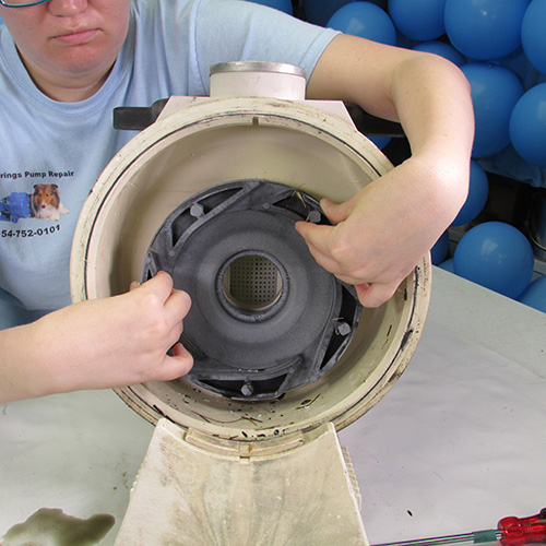
Step 6
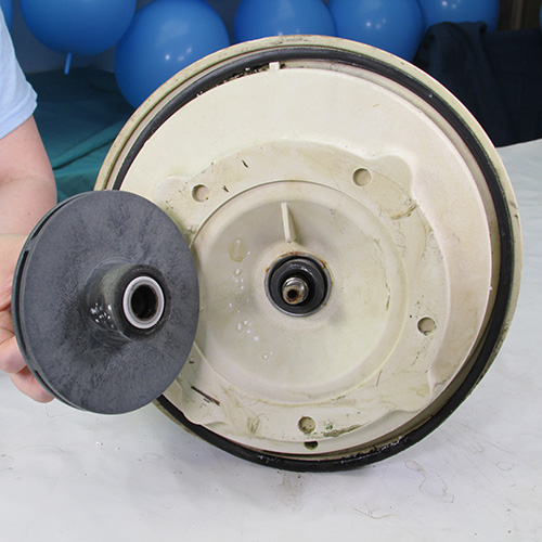
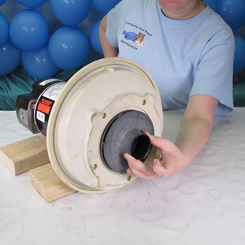
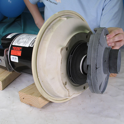
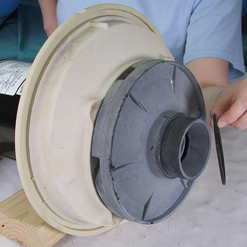
The next step we gently remove the diffuser assembly. Sometimes it can be just pulled out by hand other times it make take a little coaxing by using a small screwdriver.
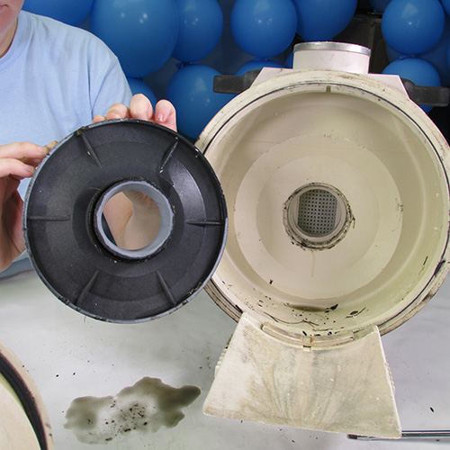
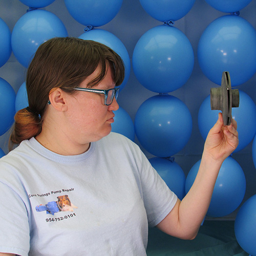
Step 7
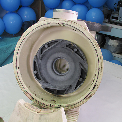
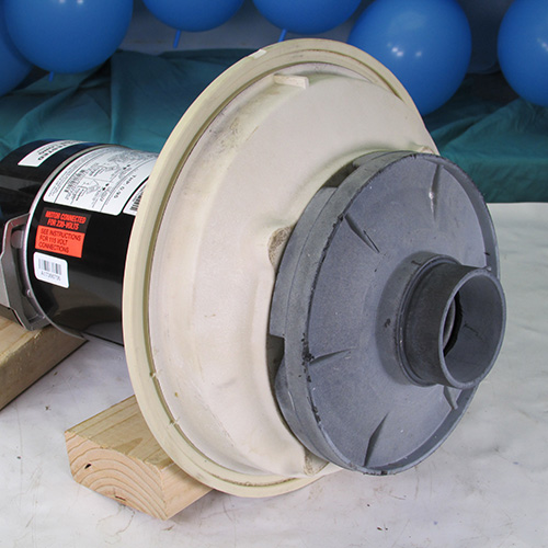
This is what the diffuser looks like when it is removed.
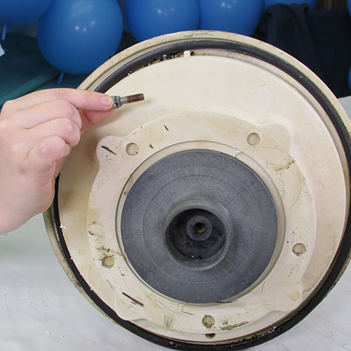
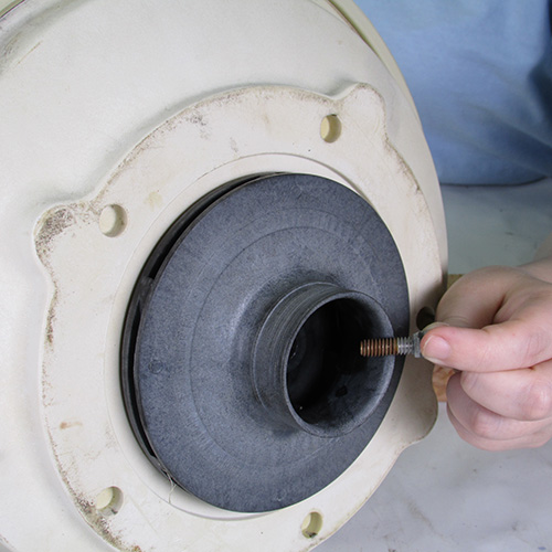
The next step is to remove the impeller locking screw. It is important to note that this screw is a reverse, or left hand, thread that means to loosen the screw you must turn it in a clockwise or right direction. Use a wrench or screwdriver as appropriate and carefully remove the screw.
Note that we have now removed the screw and pay attention to the little rubber washer behind the screwhead this is a very critical component and if this washer is missing you must replace it before reassembling the pump. If you assemble the pump without the washer or the washer is damaged the pump will leak and will result in damage to your new pump motor in a small period of time. Do not omit this step.
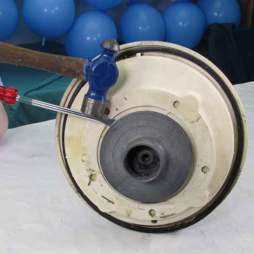
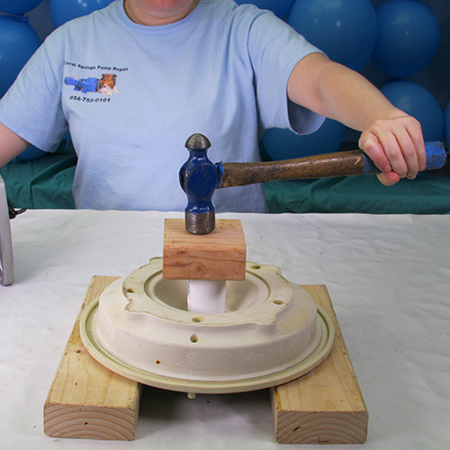
Step 8
The next step is that we have to remove the impeller. This is accomplished by turning the impeller in a counter clockwise or left orientation. One method is to use large channel lock pliers on the outer diameter of the impeller. Do not try to grip the smaller nose of the impeller. As it will most likely break off. Another method is to use a strap wrench, however the method that we found most successful is to simply insert the blade of a large flat bladed screwdriver into the edge of the impeller and strike it with a standard hammer. The resultant impact will usually loosen up the most stubborn impeller. After it is impacted we simply twist it off in a counter clockwise direction.
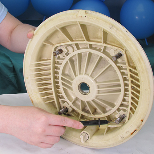
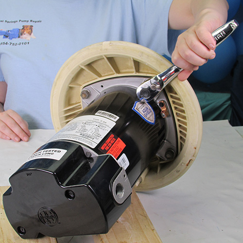
Step 9
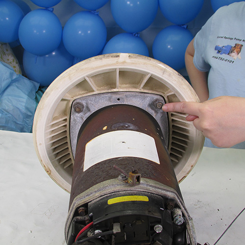
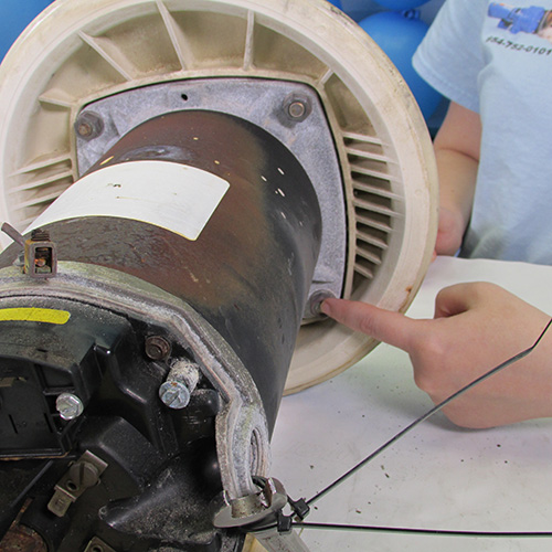
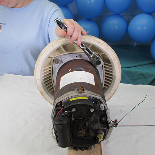
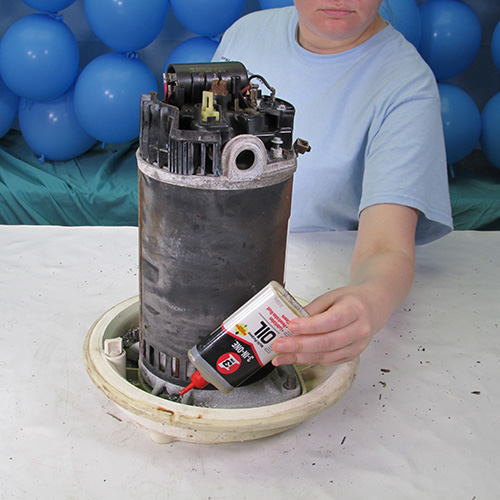
In this step we must remove the four 9/16" nuts. It helps to put a few drops of penetrating oil on each nut prior to attempted removal. This will make the job a lot easier.
Step 10
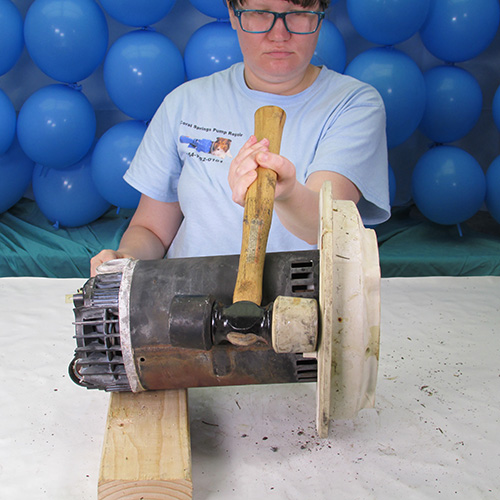
Use a ratchet wrench to make the job easier. You may have to gently tap the wrench with a mallet to impact the nuts loose. But be careful because the seal plate is made out of plastic and you do not want to crack it.
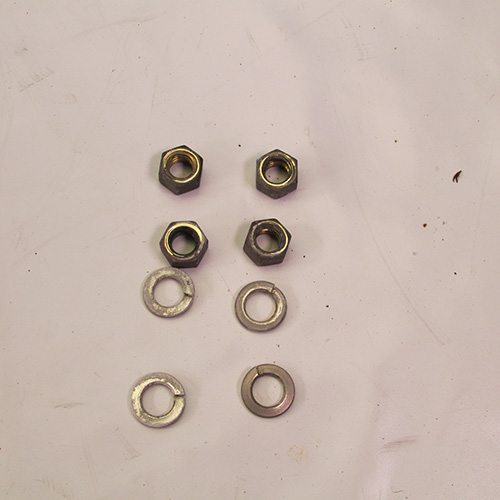
After the four bolts are removed put them in a safe place.
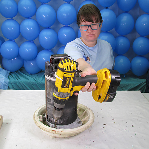
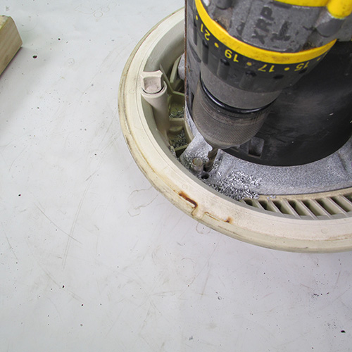
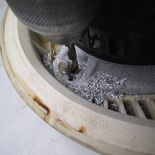
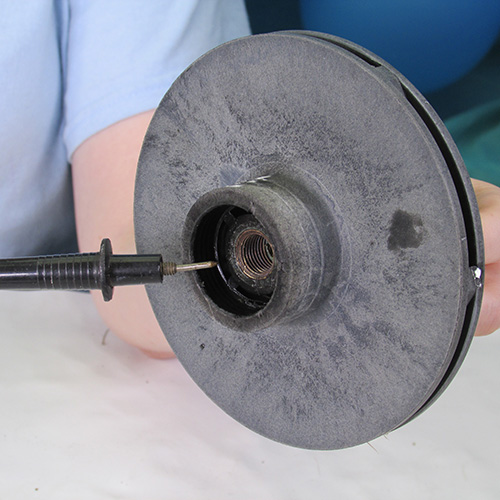
Using a soft mallet tap away the seal plate from the motor. If it does not immedietly come off stop the procedure. A very common problem with this particular brand of pump especially when they get old is that the lower studs tend to get frozen in the aluminium end bell of the motor. If you attempt to just knock off the seal plate it will usually break. So the easy way to rememdy this is to simply drill around the lower studs with a quarter inch drill as shown. The aluminum is very soft and will drill easily. After you drill out the end bell put some penetrating oil around the stud to make it easier to come off. Be careful when drilling that you don't drill too deep and make a hole in the seal plate itself. Use a drill depth gage or mark the drill to make sure you don't go too deep.
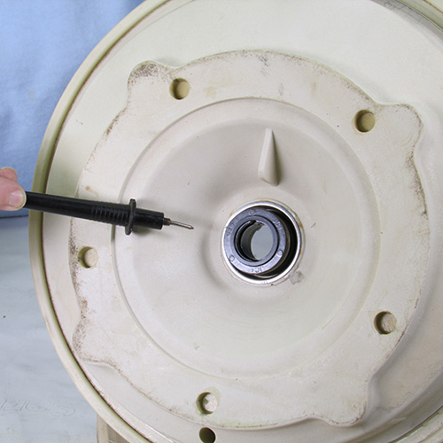
Step 11
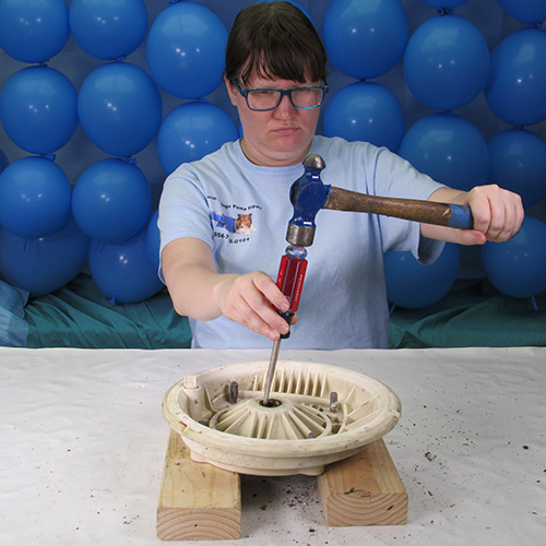
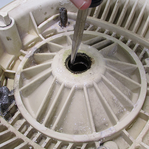
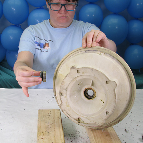
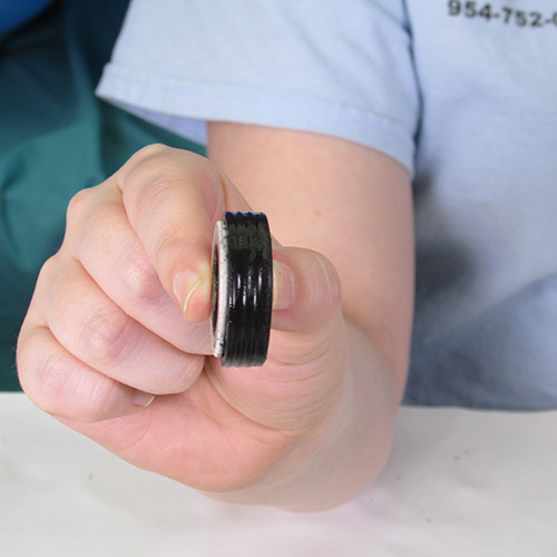
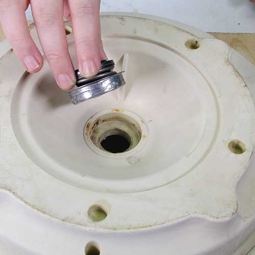
Once we have the seal plate removed from the motor, the next step is to knock out the seal head assembly. Take a flat bladed screwdriver and insert it into the seal bore as shown and tap out the seal head assembly.
This is what the seal head will look like when it comes out.
Step 12
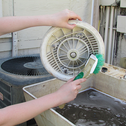
Thoroughly clean the seal plate with soap and water.
Step 13
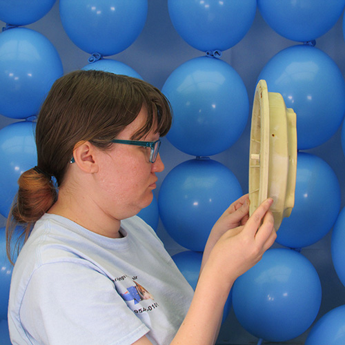
Carefully inspect the seal plate assembly for any damage. Pay particular attention to the area surrounding the seal seat assembly also known as the bore. Check for any evidence of melting or deformation. Do not use a seal plate that is damaged. If you install a damaged seal plate the seal will leak and damage your new motor. The motor will not be covered under warrenty because water damage is not covered by the manufacturers warrenty.
Inspect the seal bore.
Inspect the area around the studs for cracking.
Step 14
Inspect the impeller. Be sure there is no sign of melting or damage in the area where the seal seat goes. If there is any damage be sure to replace the impeller. If the impeller is in good shape then continue on.
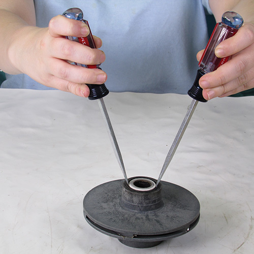
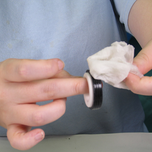
Step 15
In this step we want to remove the white seal seat from the impeller. We do this by gently prying it out with two very small screwdrivers. Alternatively you may be able to remove it by grabbing it sideways with channel lock pliers and twisting it. It is important to get all parts out including the ceramic ring and the rubber cup.
Step 16
Carefully inspect the impeller bore for any evidence of melting or heat damage.
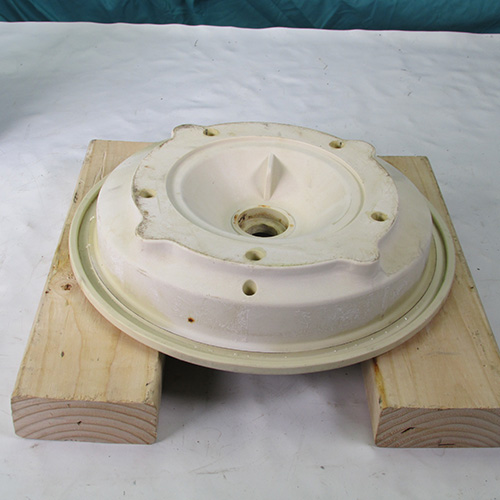
Put the seal plate down on top of two wood blocks as shown. With the seal bore pointing upwards.
Step 17
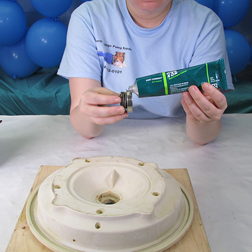
Apply a small layer of silicone RTV to the outer diameter of the seal head assembly. (the metal part only) Do not over do it--- a small amount is all that is needed. If you accidently get it on the black or carbon part clean it off immedietly with some rubbing alcohol.
Step 18
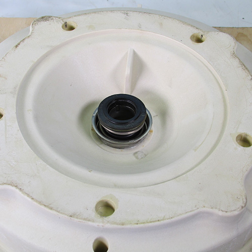
Place the seal head assembly in the seal plate bore with the black carbon part upward as shown
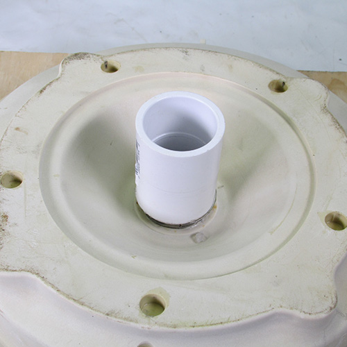
Use a 1" PVC coupling as a seal installation tool as shown.
Step 19
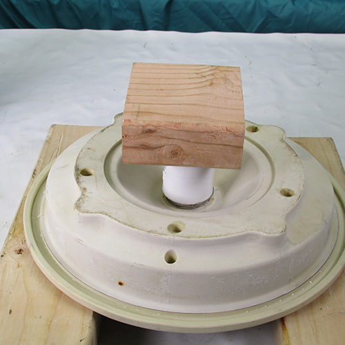
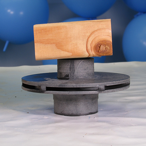
Place a block of wood on the coupling.
Gently strike the small block of wood with a small hammer. Always use proper body and eye protection when using these tools.
After the seal is installed inspect it for any damage or cracking. If it is installed properly it should look like this nice and shiny with no cracks or damage. At this time you may want to clean the carbon ring with an alcohol saturated cotton swab. It is very important that the seal mating surfaces be perfectly clean
Step 20
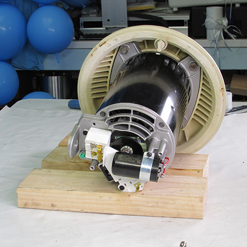
Place the seal plate on the new motor as shown.
Put in the four nuts and washers we took out previously and hand tighten them.
Using a 9/16" ratchet wrench gently tighten all four remaining nuts.
Step 21
Lubricate the seal seat rubber cup with a solution of soap and water. Do not use WD40, grease, oil, or any petroleum product. Do not use silicone or teflon. P80 or an approved rubber lubricant such as US seal Seal Lube is ok however, most do it yourselfers don't have access to it. So soap and water is the best available subsititute.
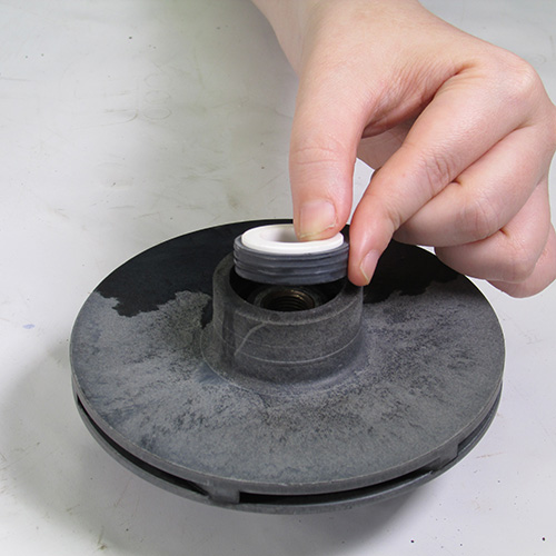
Step 22
Insert the seal seat assembly into the bore as shown.
Place a peice of paper or carboard on top of the seal and place a block of wood on top of it. Gently press down to install the seal seat in the impeller. It should not be neccesary to hammer it in, it should go in relatively easy.
After installation , inspect it to make sure it is not broken
or installed crooked,
Step 23
Next we will reinstall the impeller on to the new motor shaft. We do this by turning the impeller in a clockwise direction. Be very careful that you do not make contact with the shaft end with the seat of the seal. This could cause it to crack or break.
Turn the impeller counter clock wise hand tight is sufficient for now.
Step 24
Turn the motor and seal plate assembly upside down on a couple of blocks.
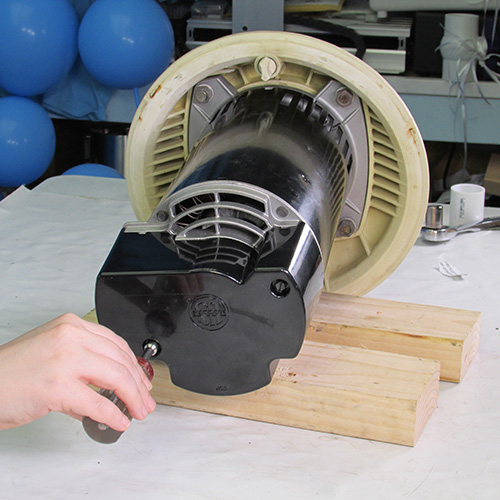
Step 25
Remove the back cover of the motor.
Insert a 7/16" wrench on the rear shaft as shown to lock it and prevent it from turning.
Using one hand hold the wrench to keep the shaft from turning and tighten the impeller in a clockwise direction with your other hand. Hand tight is sufficient
Replace the cover on the back of the motor.
Step 26
Next we will reinstall the left hand thread locking screw. Again it is very important to be sure the little rubber washer that is under the head is intact and in good condition. Place the screw in the bore and tighten it up by turning it counter clockwise or to the left.
Step 27
The next step is to replace the impeller floating eye ring. Be sure to put it on with the larger side outward. As shown here.
Step 28
The next step is to reinstall the diffuser. Simply place it into the holes as shown and gently tap it in.
Step 29
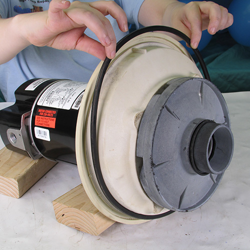
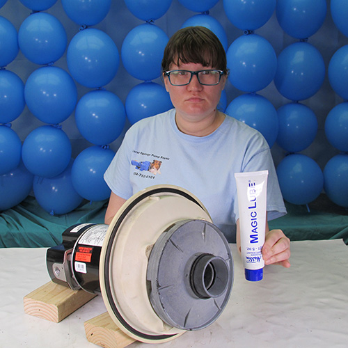
Next we will replace the two O-rings, one on the diffuser and one on the main seal plate. This is where you can use Magic Lube to secure the O-rings to the seal plate to prevent them from falling out.
Step 30
Place the power unit in proximity of the wet end as shown. Once again for this demonstation is on our bench in the real world scenario most likely the power unit will be out in the yard on the pool equipment pad.
Step 31
Slide the power unit into the front housing.
Step 32
Reinstall the stainless steel band and tighten the knob. It helps to gently tap around the perphery of the stainless steel band with a wood block to help set the O-ring and then retighten the band knob again.
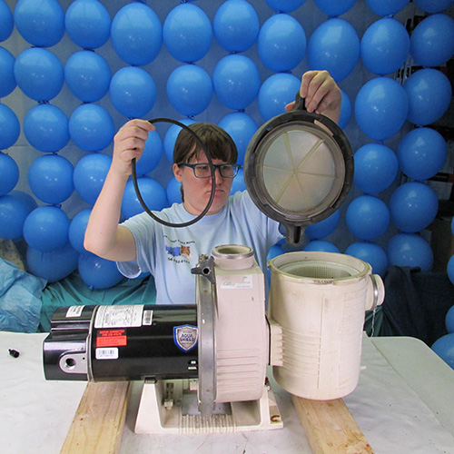
Step 33
Replace the O-ring on the basket lid assembly.
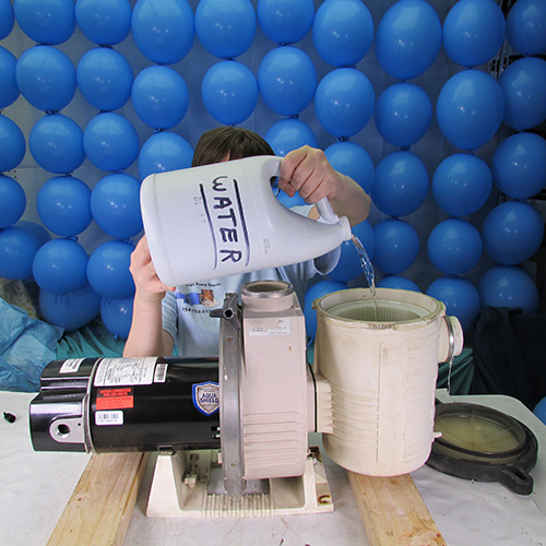
Step 34
Be sure to fill the pump with water before running it.

This instruction set applies to:
Pentair Pac Fab Ultra Flo