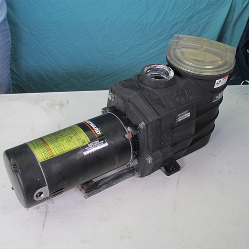
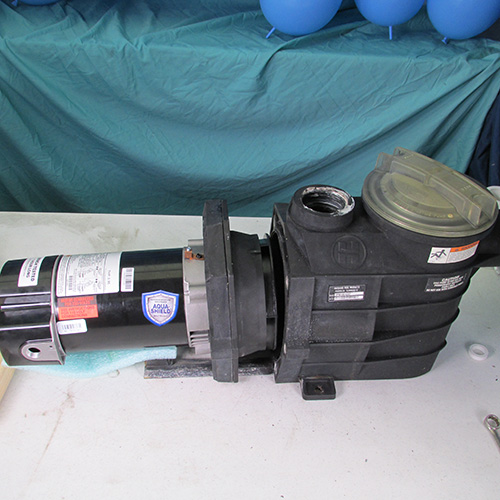
How To Change The Motor On A Hayward
Super 2 Pool Pump --- Step by Step
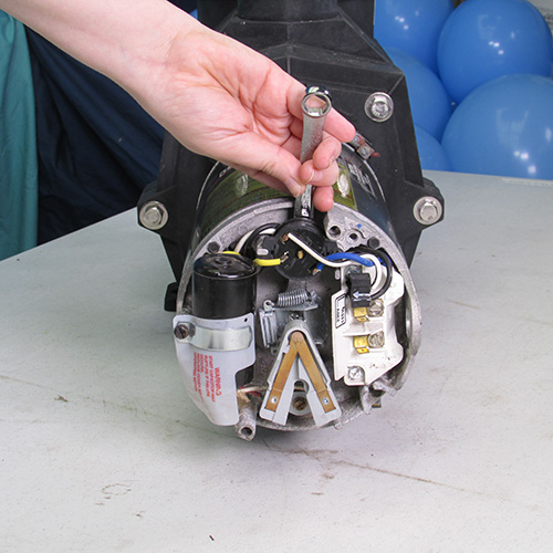


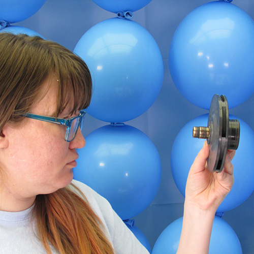
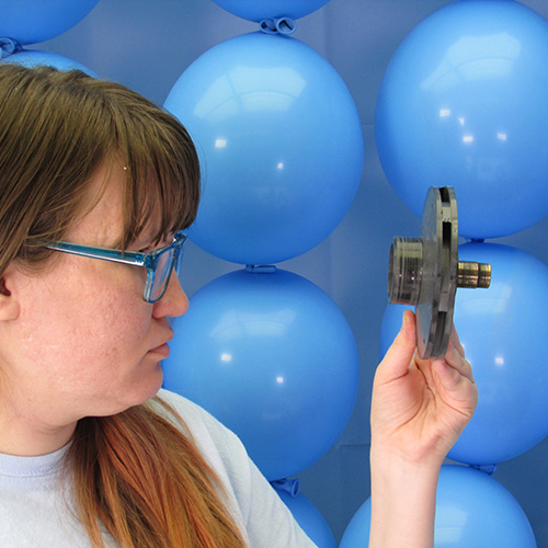
Step 1
The first step is to remove the two screws holding the back cover of the existing motor.
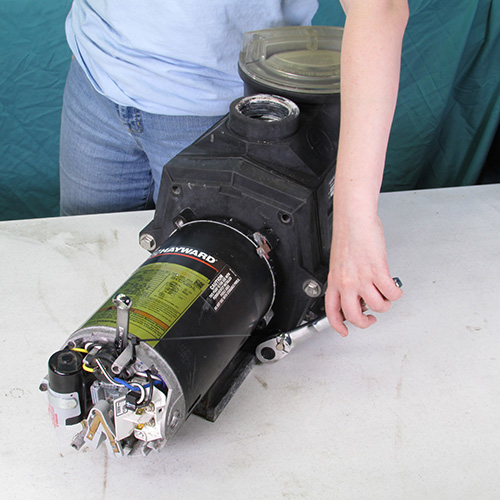
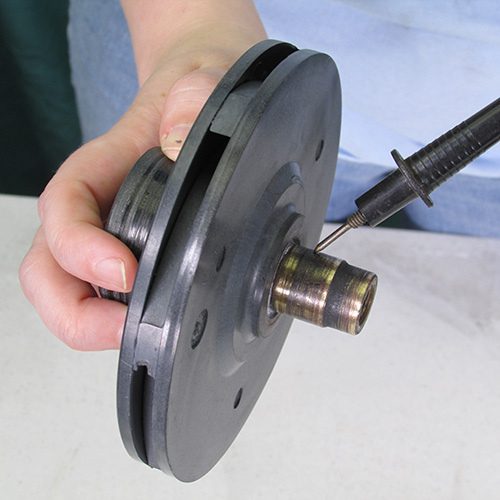
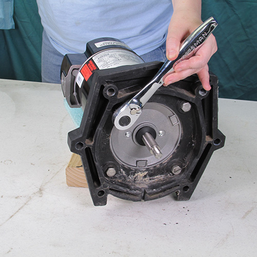
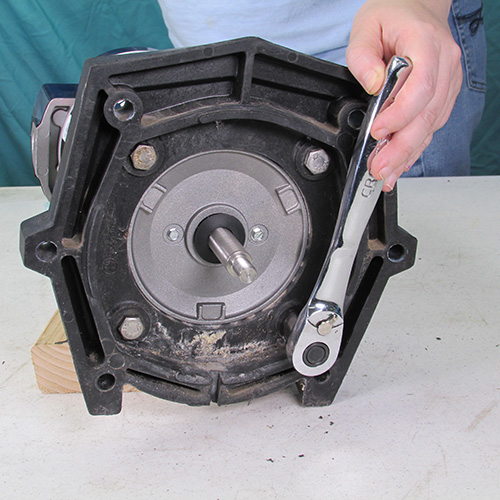
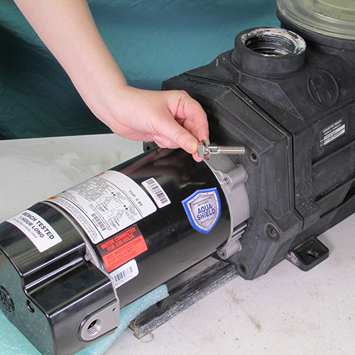
Step 2
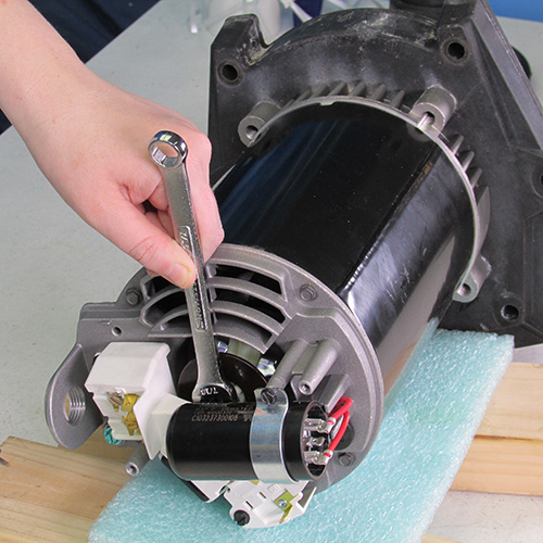
Insert a 7/16" open end wrench behind the overload switch and locking the shaft from turning as shown.
Use a zip tie to lock the wrench to the rear post of the motor this will prevent the wrench from falling out.
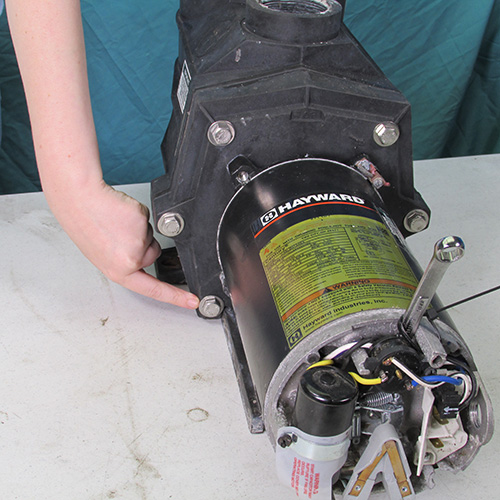
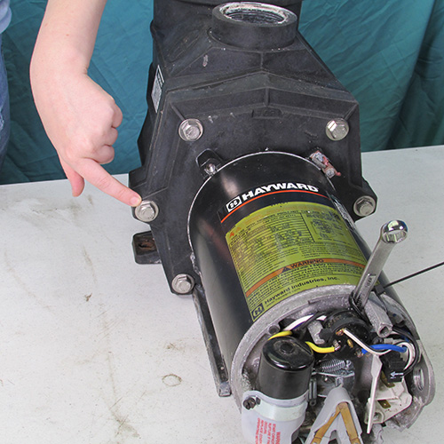
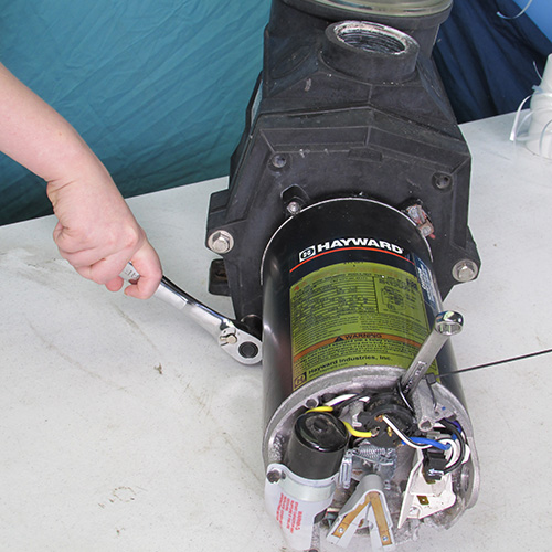
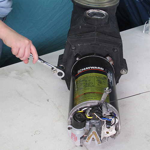
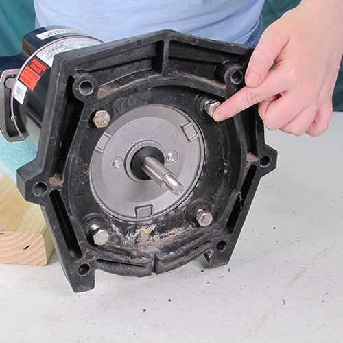
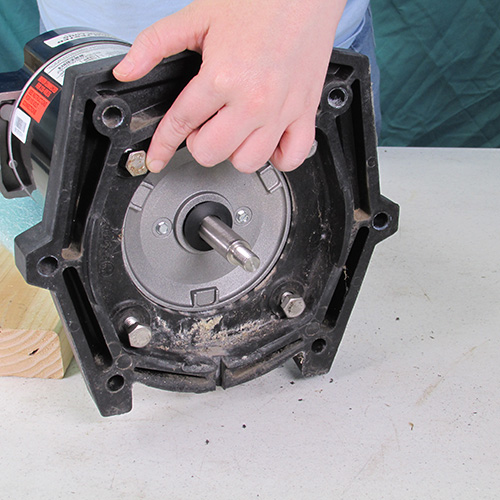
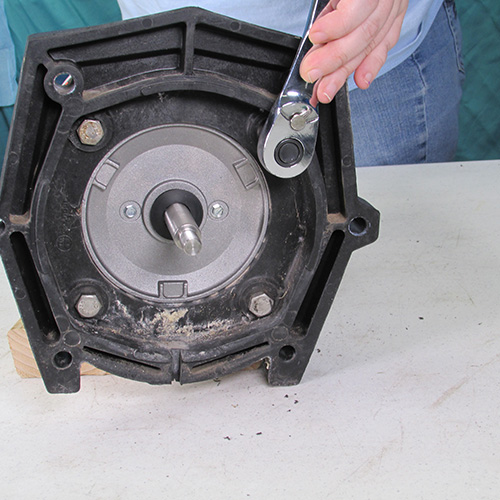
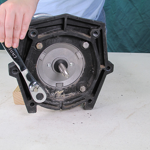
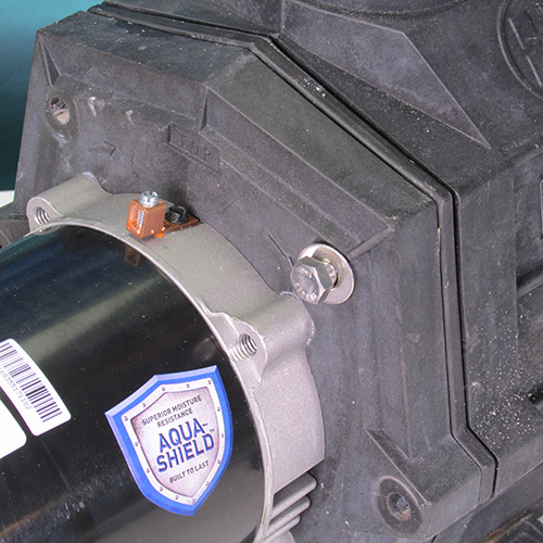
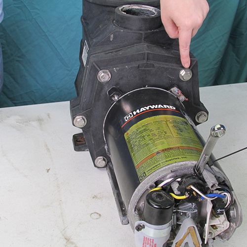
Step 3
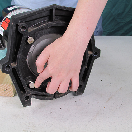
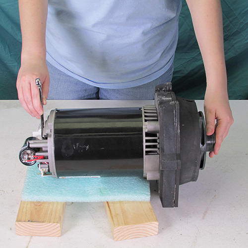
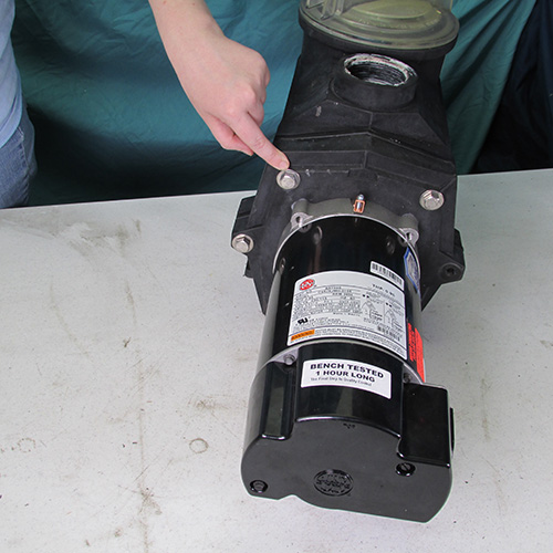
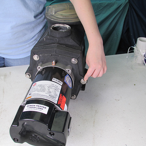
Next we will remove the 6 9/16" stainless steel bolts as shown.
Use a 9/16" wrench as shown.
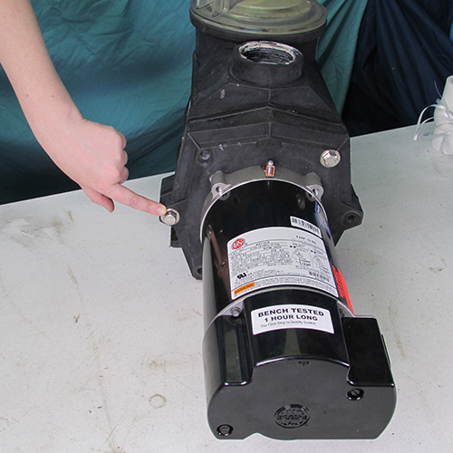
This is what the bolts should look like when they are removed. Just set them aside for now.
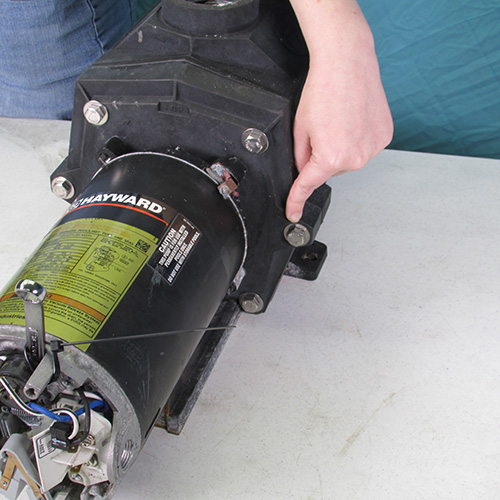
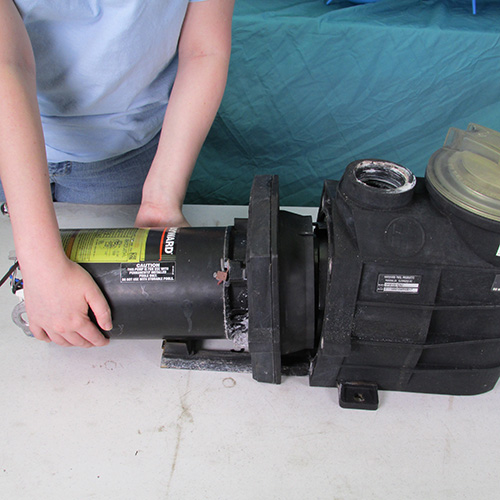
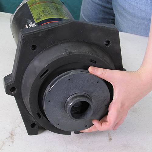
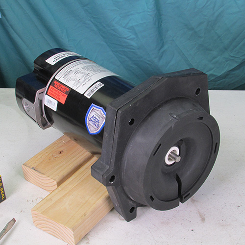
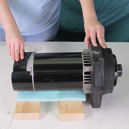
Step 4
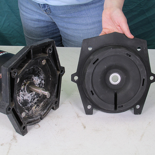
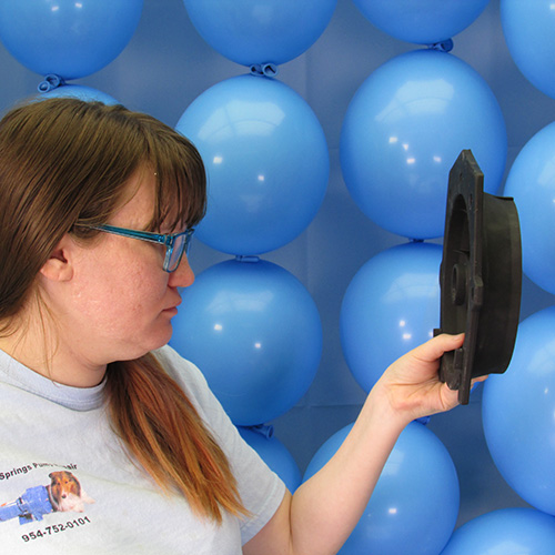
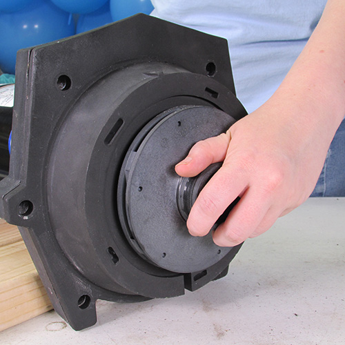
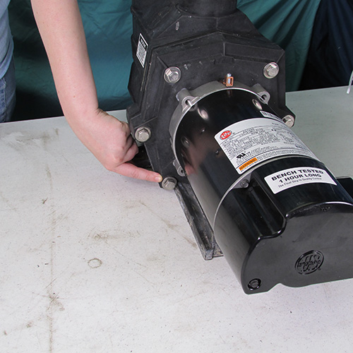
We will remove the power unit by sliding it rear-ward from the front wet end housing as shown. For the purposes of this demo we have placed the front wet end portion of the pump on the bench. In a real world scenario this would be connected to the plumbing and left in the pool owners yard.
Grasp the motor by the barrel and pull rear-ward.
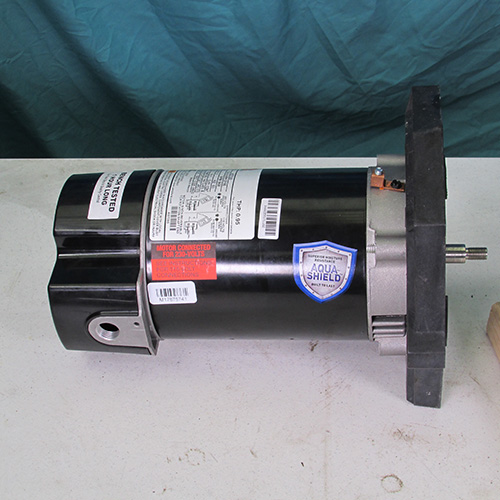
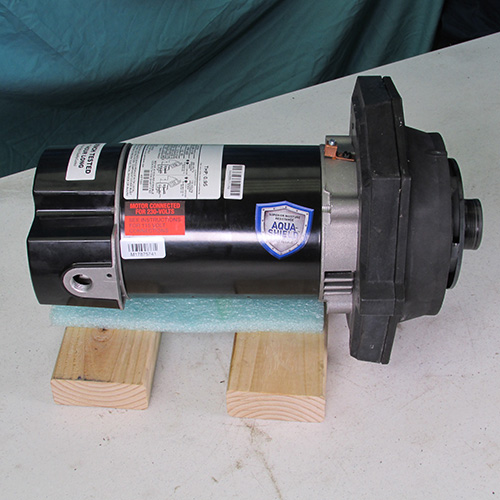
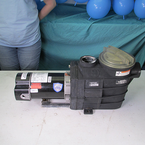
This is what it looks like when the power unit is removed.
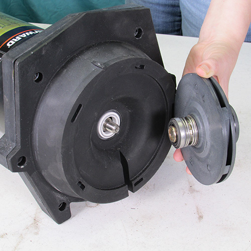
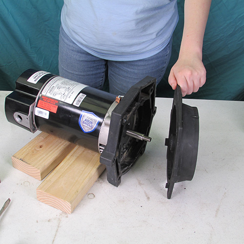
Step 5
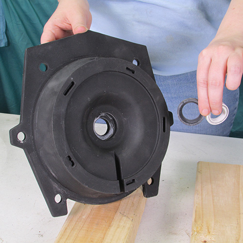
Gently remove the diffuser by prying it outward as shown. Be very careful and gentle when doing this step.
Remove the diffuser from the seal plate as shown.
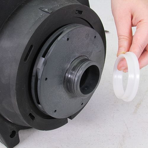
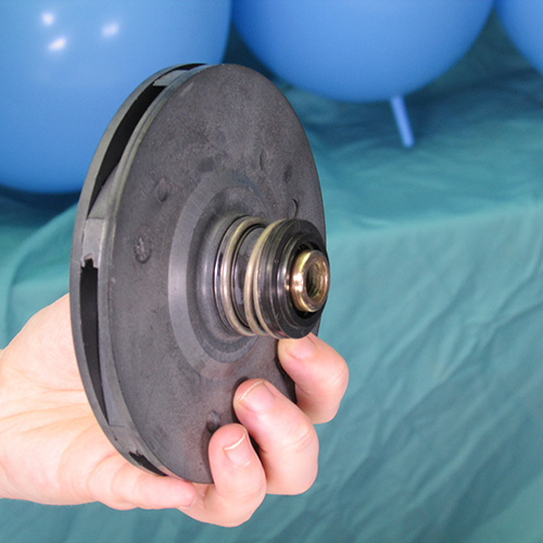
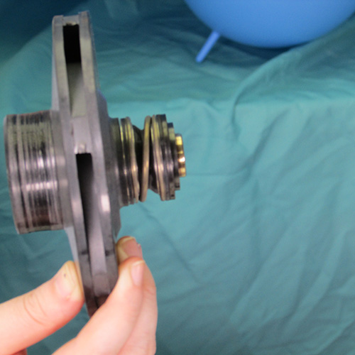
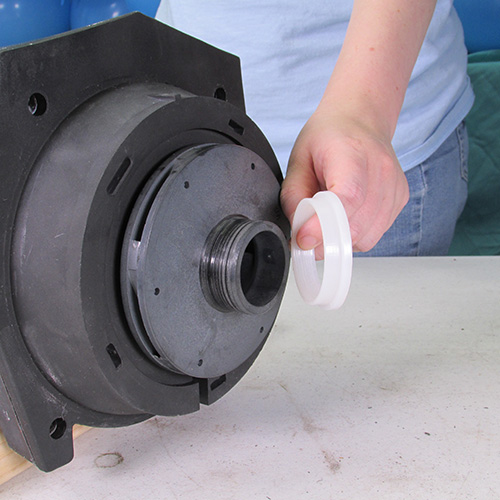
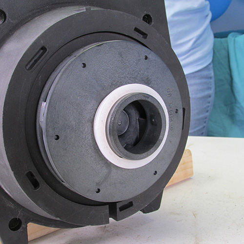
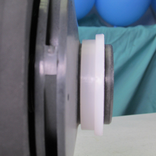
This is what the impeller will look like once the diffuser is removed, pay particular attention to the white floating ring. The larger side is placed outward as shown.
Close up detail of the impeller ring.
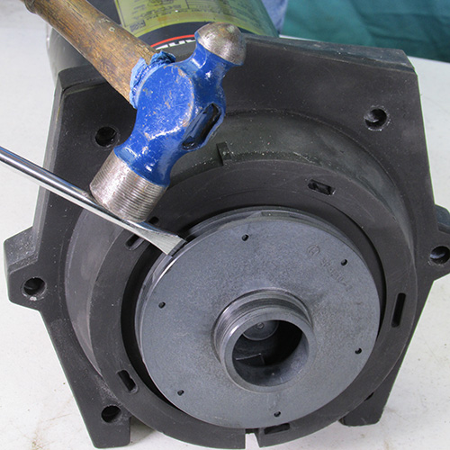
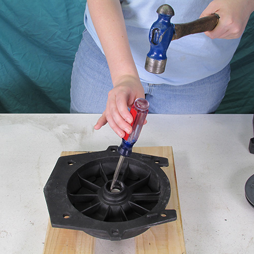
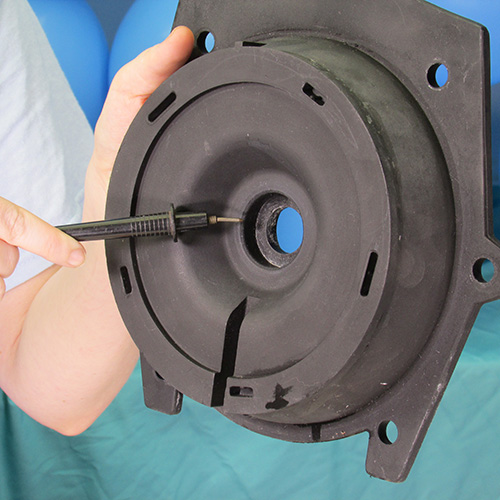
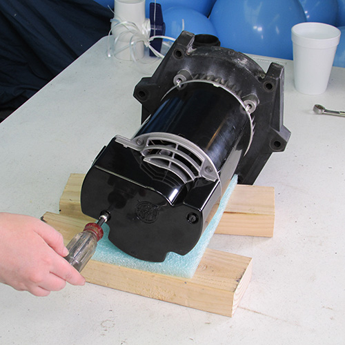
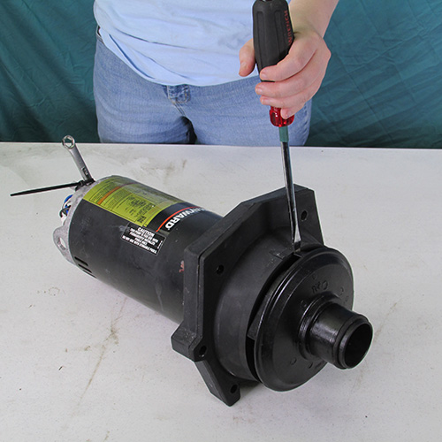
Step 6
Impeller removal: the impeller is removed by turning it in a counter clockwise direction. You can usually use a strap wrench or large channel lock pliers. Sometimes the impellers come off easy, sometimes they are stubborn. A method we found works very well to remove impellers is to insert a flat bladed screw driver and strike it with a hammer close to the impeller as shown. The resultant impact shock will loosen the most stubborn impeller. Then you can simply grasp it and turn it in a counter clockwise direction. Always use proper body and eye protection when using these tools.
The impeller will unscrew in a counter clockwise direction.
This is what the impeller looks like after being removed from the shaft.
Step 7
Remove the seal plate from the mounting ring as shown it will usually just slide right off. If it is stubborn gently insert a couple of screwdrivers in the crack between the seal plate and the mounting ring and pry forward. Be careful that you don't crack anything.
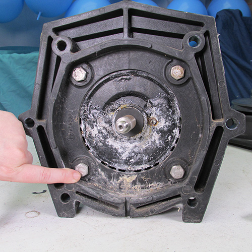
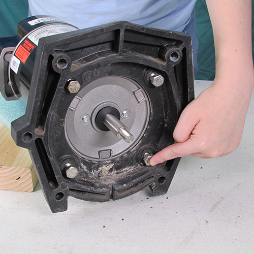
Step 8
Next we will remove the four mounting bolts holding the mounting ring to the motor. This may be a difficult challenge because sometimes the bolts are corroded into the motor and may be difficult to remove.
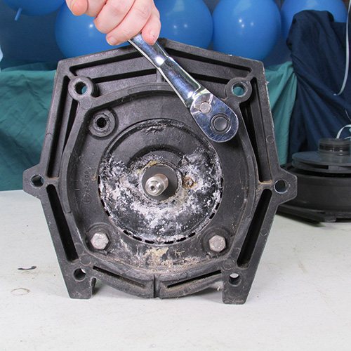
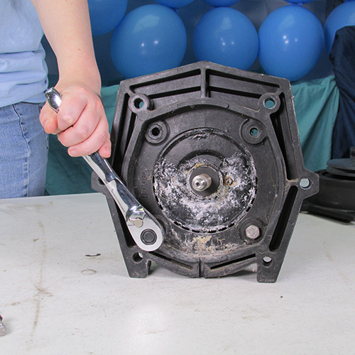
Step 9
Use a 9/16" wrench to remove these bolts in a counter clockwise direction. If the bolts are stubborn you may have to tap the wrench handle with a mallet to impact the bolts. If you have an electric or air impact wrench it will make the job much easier.
Step 10
Once the four bolts are removed, separate the mounting ring from the motor by pushing it forward it should come off very easy however if it is stubborn gently tap it with a soft mallet or block of wood. Do not use a metal hammer.
Step 11
At this point you can discard the old motor or, if you are only doing a seal replacement only, you can put it away for reinstallation later.
Step 12
At this point it would be good to set these parts aside and prepare for reassembly.
Step 13
Next we must remove the old seal from the impeller. We do this by grasping the seal with channel lock pliers and twisting it off.
Step 14
It is very important to make sure that all parts from the old seal are removed from the impeller shaft. Sometimes when removing the old seal it will break apart in pieces be sure to remove all remnants of the old seal.
Step 15
Do a very thorough inspection of the impeller and be sure it is free of debris and inspect the surface of the shaft to be sure it is clean and smooth. It may be advisable to clean the shaft surface with brillo, sos, or a scotch brite pad.
When inspecting the impeller be sure to pay attention to this area to be sure nothing is stuck on there. Sometimes the O-ring from the old seal head will remain, be sure to remove it.
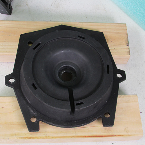
Step 16
In this step we will remove the seal seat assembly from the seal plate.
Place the seal plate on a couple blocks of wood as shown.
Using a hammer and screw driver gently tap the seal seat out of the seal plate.
Once it is removed it will look like this. Make sure you get all pieces of the seal seat out, that includes the white ceramic portion and the round rubber portion.
Step 17
Make a thorough inspection of the seal plate pay particular attention to the center hole where the seal seat was installed check for any discrepancies such as deformities caused by melting from excessive heat. Do not use a seal plate that is damaged.
Step 18
At this step its best we wash the seal plate before installing the seal seat assembly. The seal plate must be clean.
Pay particular attention to this area.
Clean the shaft of the impeller with a brillo pad or a scotch brite or sos soap pad. The later model impellers have a brass shaft extension, The older ones were plastic. You may want to upgrade to a brass one by purchasing a new impeller. Both are acceptable, however the brass is more durable
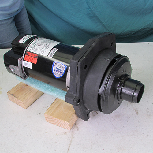
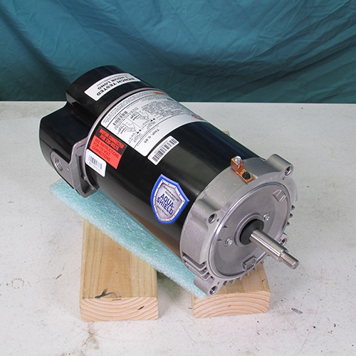
Step 19
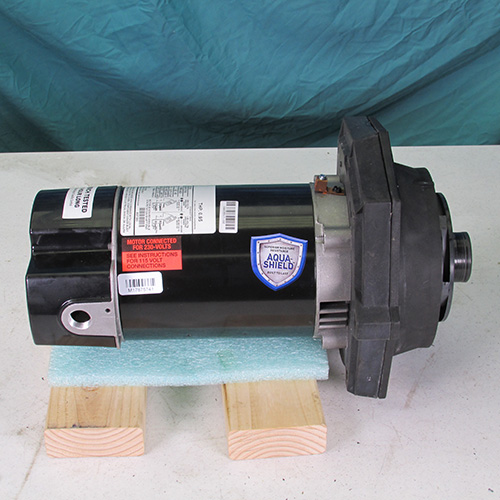
Take the new motor out of the box and set it on your bench and set it on a couple of blocks as shown.
Step 20
Position the seal plate to the front of the motor as shown.
Step 21
Next we will install these four 9/16" bolts as shown.
Tighten them firmly with a 9/16" wrench.
Step 22
Lay the seal plate assembly on your bench as shown.
Step 23
Remove the seal seat from the box and lubricate the seal seat with soapy water as shown. Do not use grease, oil, Magic Lube, WD40, or any petroleum based product.
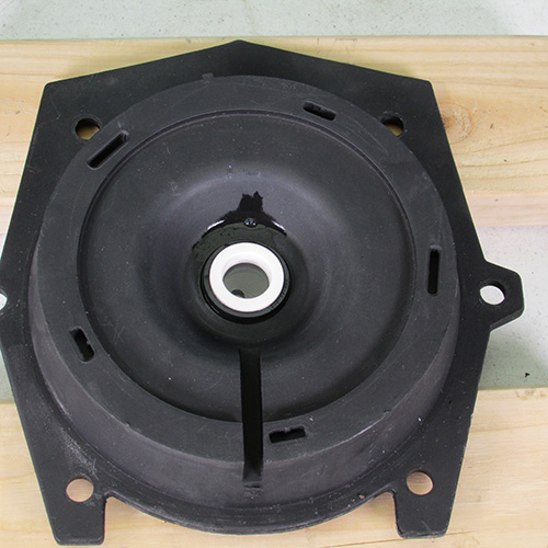
Step 24
Place the lubricated seal seat on the seal plate as shown and press into place. Use the rounded butt of a screwdriver.
Step 25
Place the seal plate back against the mounting ring as shown and snap into place. Use due care so the motor shaft does not make contact with the white seal seat during this process.
Step 26
Lubricate the center of the seal head assembly with soapy water do not use grease, oil, wd40, Magic lube, silicone or any petroleum based product.
Step 27
Carefully place the seal head assembly on the impeller shaft and push it on using a twisting motion.
This is what it should look like when it is installed. Be sure it is seated all the way down as shown.
Step 28
Using a cotton tipped swab clean the seal head assembly ring with rubbing alcohol.
Step 29
Using a cotton tipped swab clean the seal seat assembly ring with rubbing alcohol.
Step 30
Next we will install the impeller by turning it in clockwise direction use due care to be sure that the carbon ring of the seal head does not make contact with the motor shaft during this procedure. Work very slowly and carefully.
Step 31
Tighten up in a clockwise direction hand tight is sufficient for now.
Step 32
Turn motor upside down as shown. Support the bottom on a couple of blocks and insert a soft pad so as not to scratch the motor.
Step 33
Remove rear cover screws and remove rear cover.
Step 34
Insert a 7/16" wrench as shown to lock the shaft from turning.
Step 35
While holding the shaft wrench with one hand use the other hand to tighten the impeller in a clock wise direction. Hand tight is sufficient.
Step 36
Replace back cover on motor.
Turn motor right side up.
Step 37
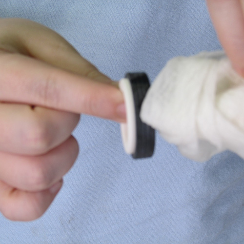
Install the floating impeller eye ring as shown. Be sure the large side is pointing outward as shown.
Close up of side of impeller eye ring notice the large side is pointing outward.
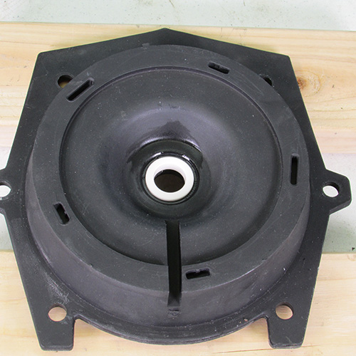
Step 38
Install diffuser as shown.
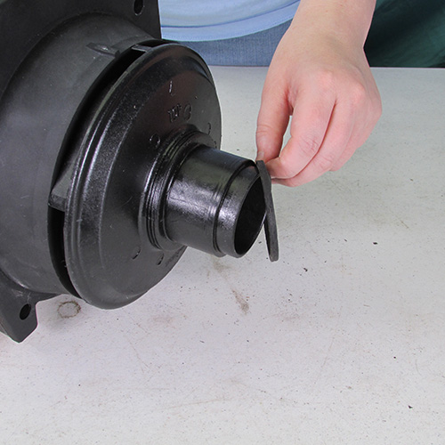
Acquire diffuser O-ring.
Step 39
Install diffuser O-ring on diffuser nose.
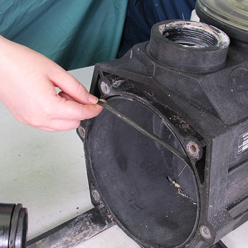
Step 40
Replace pump body O-ring. This is really a flat band type ring it looks like a large rubber band.
Step 41
Slide rear power unit into the front wet end assembly as shown.
Step 42
Reinstall the 6 9/16" bolts we uninstalled previously.
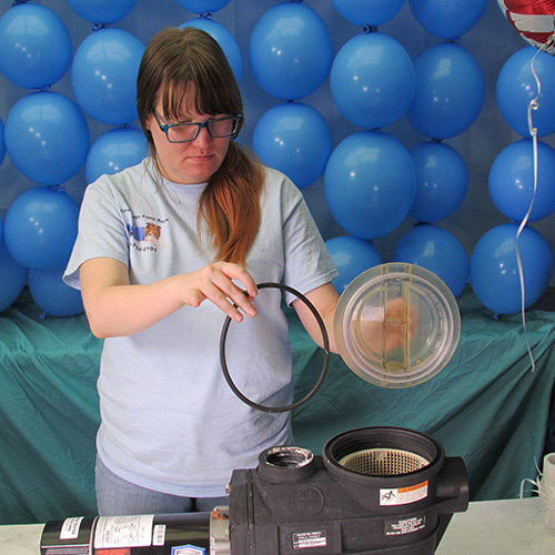
Step 43
Install a new O-ring on the basket lid.
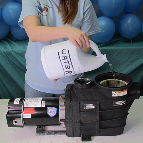
Step 44
Always fill the pump basket with water before running 1 to 2 gallons should be sufficient.
These images are in High Definition
Right click and open in new tab for
detailed inspection
These instructions apply to these model numbers: SP3007EEAZ, SP3010EEAZ, SP3015EEAZ, SP3020EEAZ, SP3025EEAZ, SP303063AZ, SP3005X7AZ, SP3007X10AZ, SP3007X10AZ, SP3010X15AZ, SP3015X20AZ, SP3020X25AZ, SP3025X30AZ, SP3010X152AZ, SP3015X202AZ, SP3020X252AZ