How To Change The Motor & Seal On A Hayward Superpump & Maxflo
Step 1
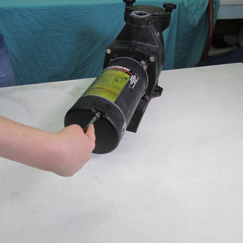
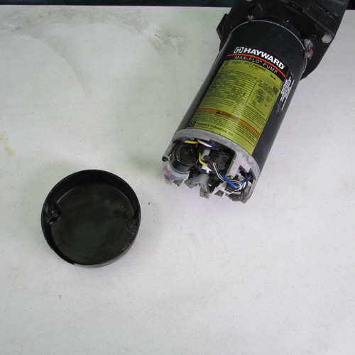
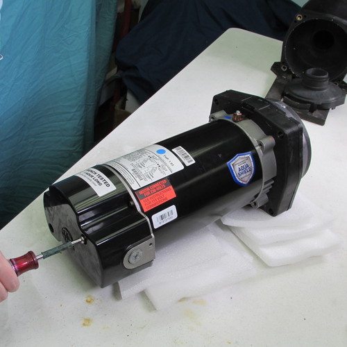
First we remove the two screws holding on to the rear cover of the motor and gently remove the rear cover. If the cover is stuck, tap it rearward at the seam with a screwdriver or chisel. Use caution, the metal on rear cover can be sharp, it is advisable to wear leather gloves. If the screws are rusted or stuck, you may have to drill them out, or shear them off with a sharp chisel...Again , use caution and use proper body and eye protection when using those tools
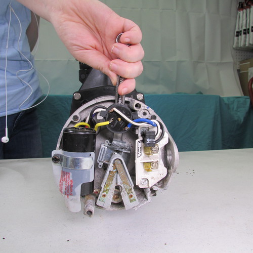
Step 2
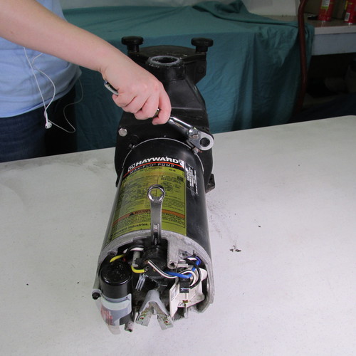
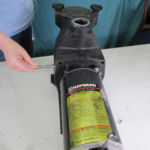
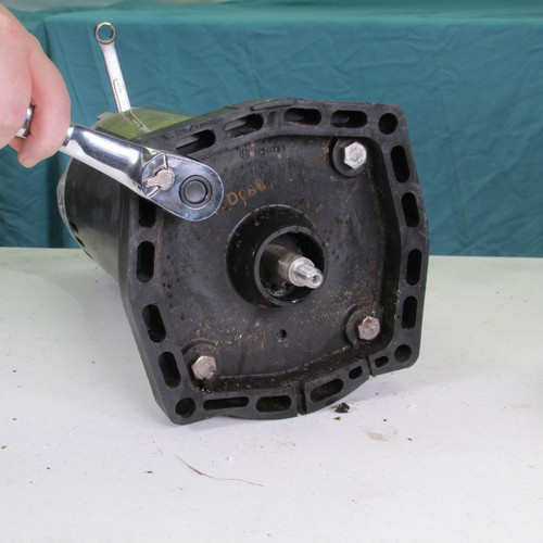
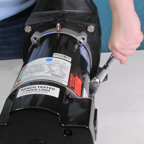
We insert a 7/16" wrench behind the overload switch to lock the motor shaft from turning. If you have a zip tie you can attach it around the wrench and the post of the motor to hold the wrench from falling out
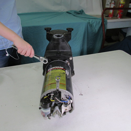
Step 3
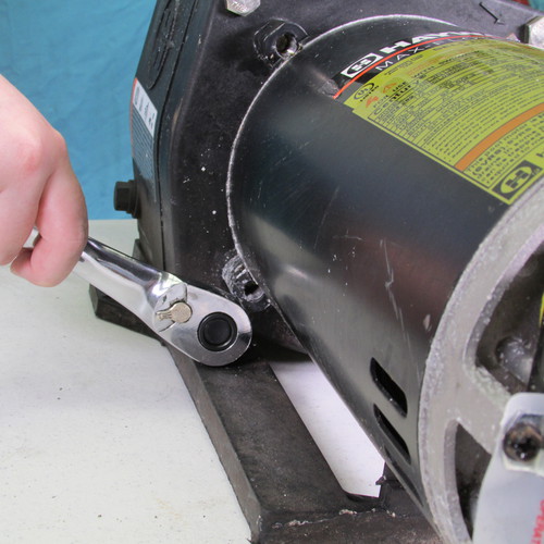
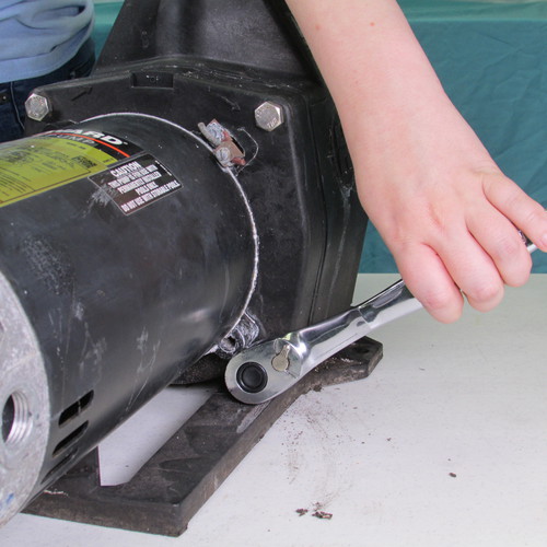
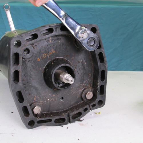
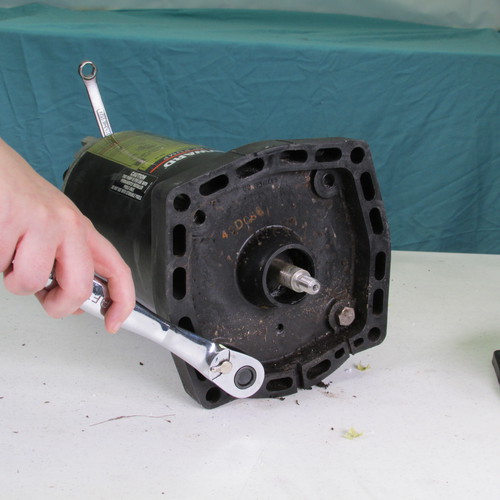
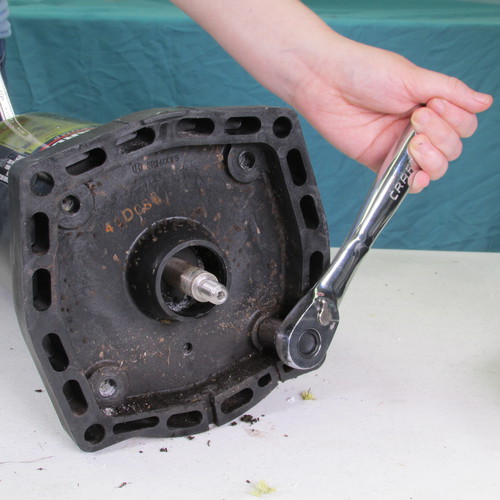
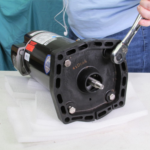
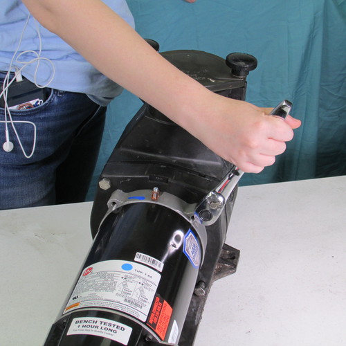
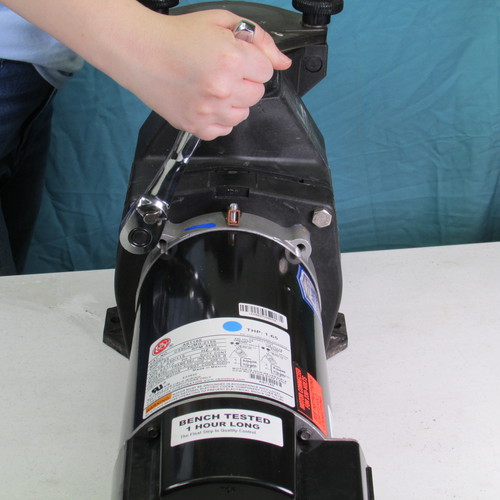
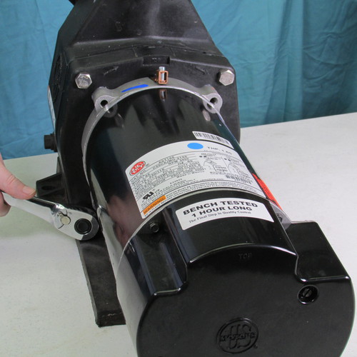
Remove the four 9/16" bolts with a wrench as shown.
Step 4
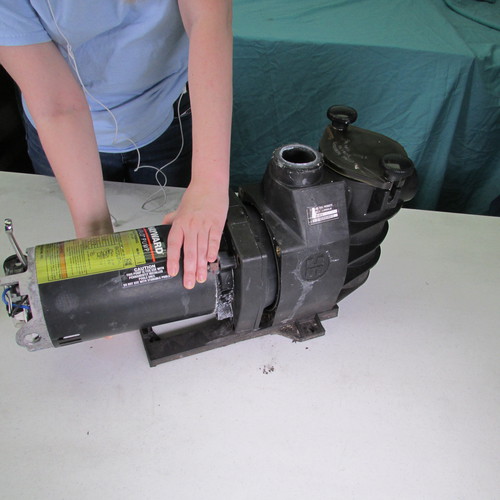
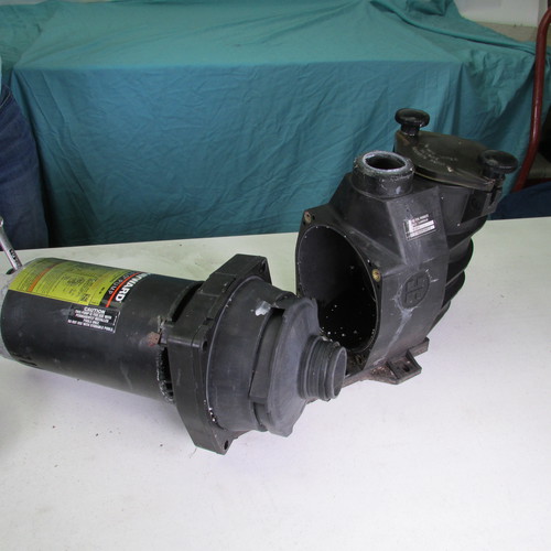
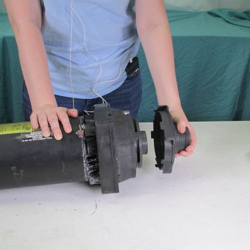
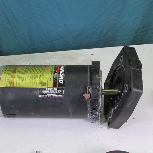
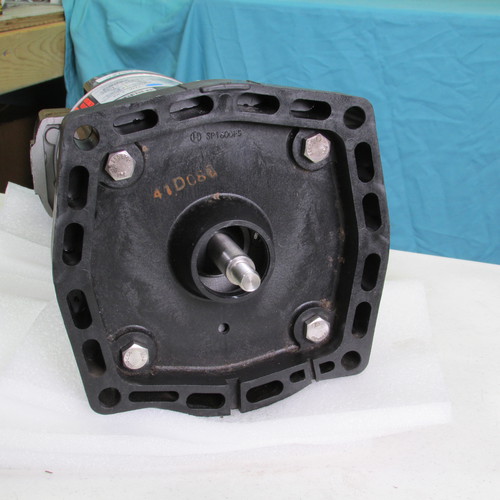
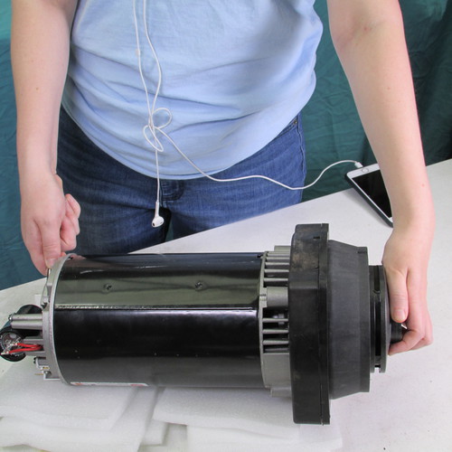
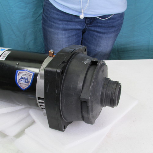
After the four bolts are removed, grasp the barrel of the motor assembly and pull rear-ward. This should dislodge the power unit as shown.
Step 5
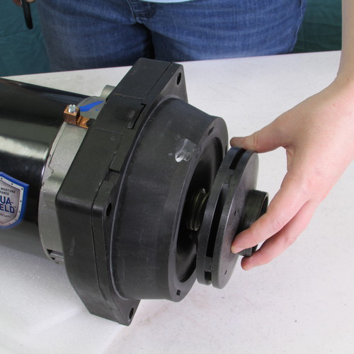
The next step is to remove the diffuser by pulling it forward.
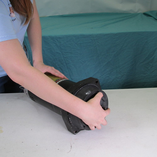
Step 6
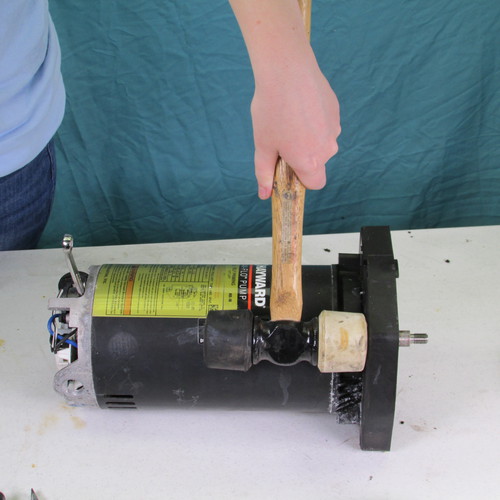
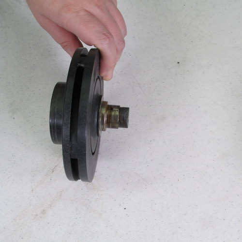
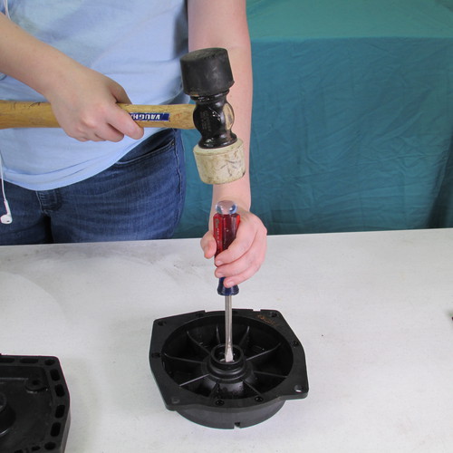
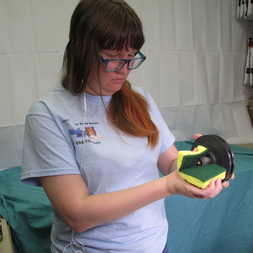
Next we will attempt to remove the impeller by grasping it firmly and turning it in a counter clockwise direction. Sometimes the impeller comes off very easily and other times they can be stubborn.
If the impeller does not turn off easily by hand you can try to use channel lock pliers or a strap wrench: However a method that we find very successful is to insert a large flat bladed screw driver into the edge of the impeller and strike the screwdriver with a hammer. Always use proper body and eye protection when using these tools.
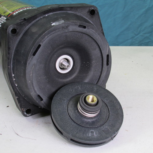
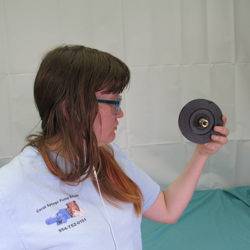
This is what it will look like when the impeller is removed.
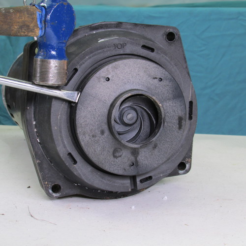
Step 7
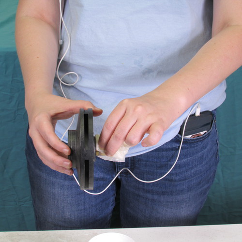
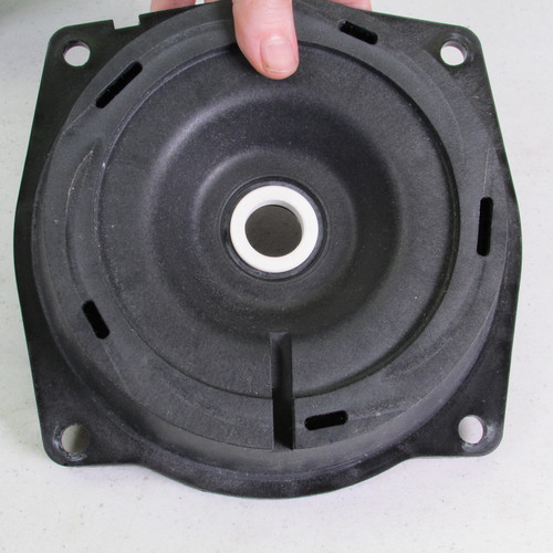
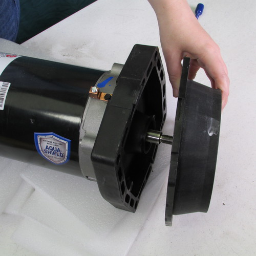
The next step is to remove the seal plate. It should simply come right off be sure to note the orientation as to top and bottom usually there will be a mark that says top however it may be advisable to mark the top of the seal plate and mounting ring so you can reassemble it properly.
Step 8
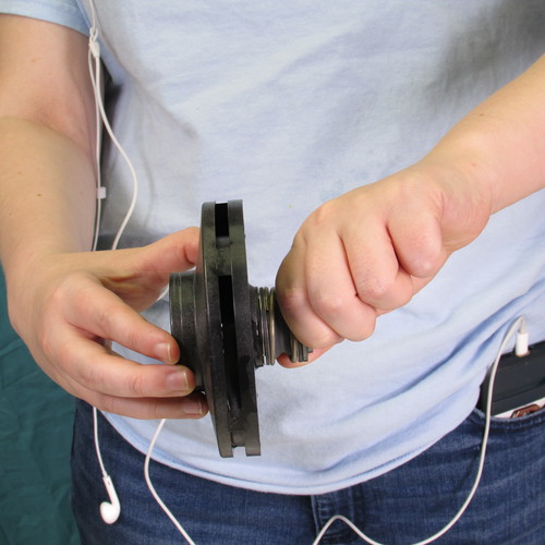
Remove the four bolts holding the mounting plate. This may easy or it may be difficult you may have to tap the wrench gently with a hammer or mallet to impact the bolts loose. If you have an electric or air impact wrench it can make the job easier.
Step 9
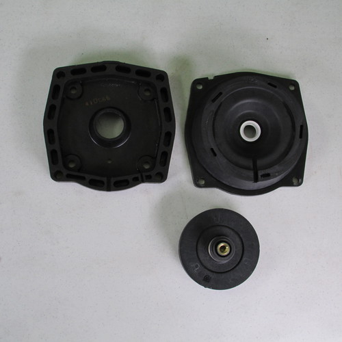
Gently tap the mounting ring away from the motor use a soft mallet. Do not use a metal hammer.
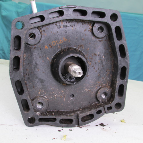
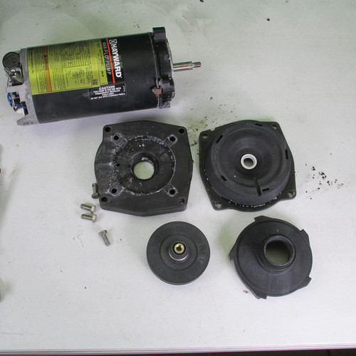
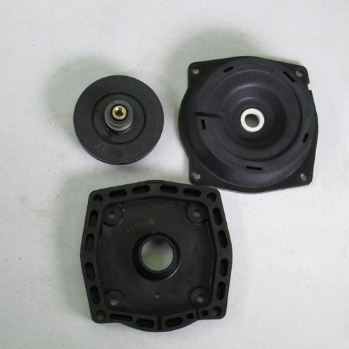
Once everything is disassembled this is what it should look like.
If you are installing a new motor at this point you can discard the motor. If you are only doing a seal then put the motor aside to reinstall later.
Step 10
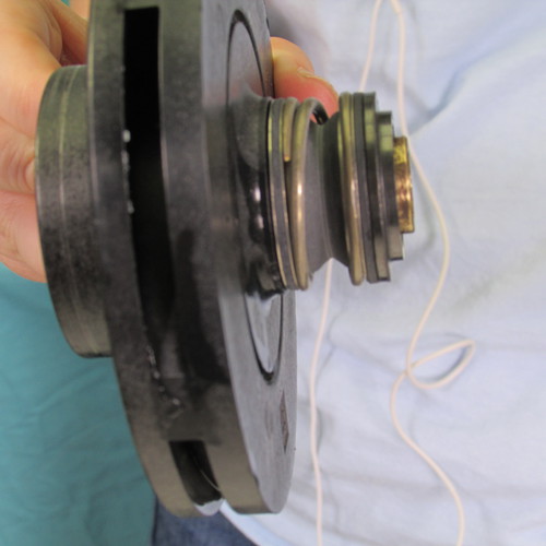
Remove the seal from the impeller with large channel lock pliers. Grasp the impeller firmly in one hand and twist the seal off with your other hand.
Be sure to remove all parts of the seal, notice in this photo there is still a metal part left from the seal be sure to remove this.
If you look closely you will see there is a rubber washer left over from the old seal this too needs to be removed.
This is what it looks like when all the parts from the seal are removed. Notice there is nothing on the shaft.
Step 11
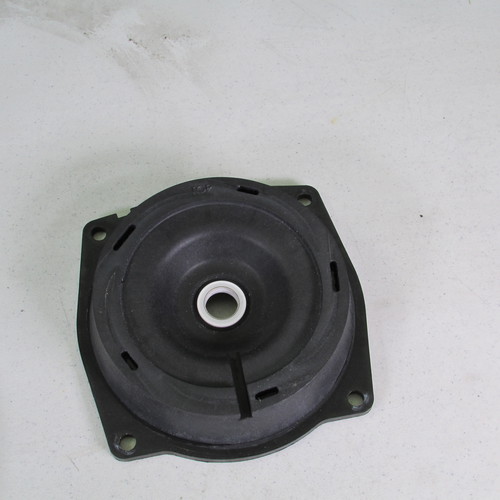
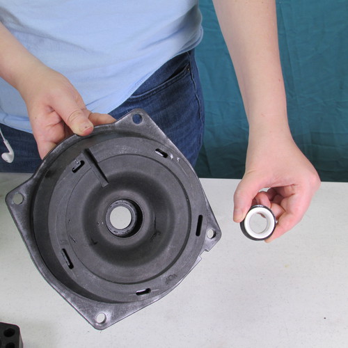
Next we will remove the old seal seat from the seal plate assembly.
Turn it over as shown.
Insert a flat bladed screwdriver on the seal seat as shown and gently tap it downward this will dislodge the seal seat and knock it out of the seal plate.
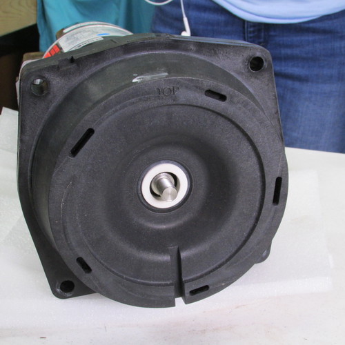
This is what it looks like when the seal seat is removed from the seal plate.
Step 12
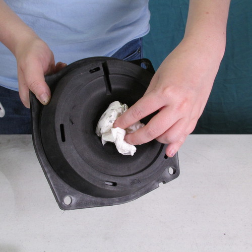
Carefully clean the seal plate assembly in the area where the seal is installed. (near the center hole)
Step 13
VERY IMPORTANT
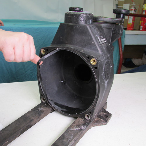
Carefully inspect the seal plate assembly for any evidence of damage caused by excessive heat such as melting, warpage, cracking, etc. Do not use a damaged seal plate. It will cause the new motor to fail prematurely replace the seal plate if there was any question.
Step 14
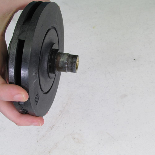
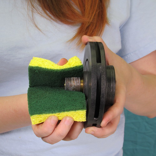
Using a scotch brite or brillo pad carefully clean the shaft on the impeller.
You will notice the shaft extension is brass. Some of the older impellers had a plastic extension. If yours is plastic you may want to upgrade to brass.
The new impellers and interchangable with the old and are more durable
Step 15
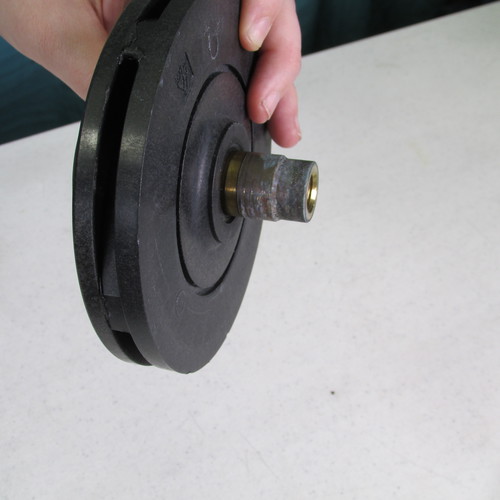
Carefully inspect the impeller check for signs of damage to the shaft and inspect the vanes for evidence of clogging with debris. If there is debris in the vanes remove it with a stiff wire such as a piece of wire coat hanger.
Step 16
Lurbricate the impeller shaft with soapy water in preparation of seal installation. Do not use oil, grease, Magic Lube, or WD40. A rubber lurbicant such as P80 is ok but do not use any petroleum based product. Do not put silicone RTV on the seal.
Using a twisting motion grasp the seal and push on to the impeller shaft as shown.
Step 17
This is what it looks like when the installation is complete. Be sure that it didn't get cracked or damaged during installation.
This is a side view it should look just like this.
Step 18
Lubricate the seal seat assembly with some soapy water do not use oil, grease, Magic Lube, WD40, or silicone RTV or any petroleum based product. A rubber lubricant such as P80 is ok.
Step 19
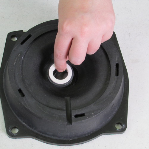
Insert the seal seat assembly into the seal plate as shown.
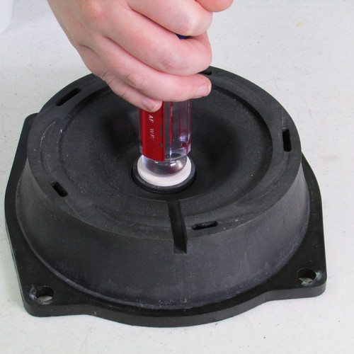
Press the seal seat assembly into the seal plate as shown with the butt of a clean screwdriver.
This is what it should look like when its complete.
Carefully inspect both sides of the seal plate assembly make sure the seal seat is properly installed that it is firmly seated and not crooked and not cracked or damaged.
Step 20
These parts should be ready for reassembly.
Step 21
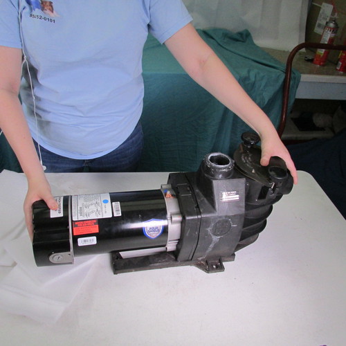
Take your new motor out of the box and set it on the bench for assembly. If you are just doing a seal replacement on your exisiting pump then now is the time to recover the old motor you set aside.
Step 22
Place mounting ring on to the motor as shown. Make sure the top of the mounting ring is aligned with the top of the motor. The mounting ring should say TOP on the rear surface.
Step 23
Install the four 9/16" by 7/8" long bolts and tigheten with a wrench as shown.
Step 24
Insert seal plate on top of mounting ring as shown. Be sure to align the top orientation on the seal plate to the top oritnation of the mounting ring, if you look closely you will see the words "top".
Step 25
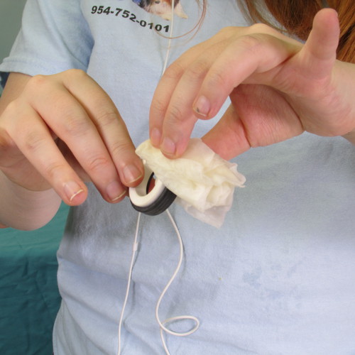
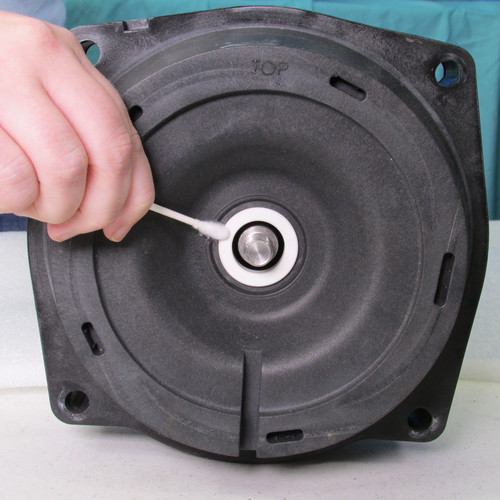
Using a Q-tip cotton swab clean the seal seat with rubbing alcohol. This is a very important step if the seal surfaces are not clean they will fail in a short time.
Using a Q-tip cotton swab clean the seal head with rubbing alcohol. This is a very important step if the seal surfaces are not clean they will fail in a short time.
Step 26
Step 27
Carefully place the impeller on the shaft as shown. Use caution so you do not allow the seal head assembly to come in contact with the shaft allowing it to get damaged. Work slowly and carefully.
Turn the impeller in a clockwise direction. Hand tight is sufficient for now.
Step 28
Remove the back cover of the new motor.
Step 29
Insert a 7/16" wrench as shown to lock the shaft of the motor to prevent it from turning.
Step 30
While holding the wrench with one hand gently turn the impeller in a clockwise direction with one hand.
Tighten it up hand tight
Step 31
Remove the wrench and reinstall the back cover.
Step 32
Aquire a gasket and O-ring set for the pump assembly.
Step 33
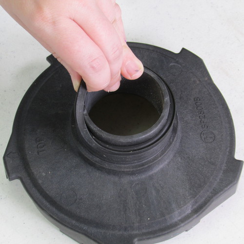
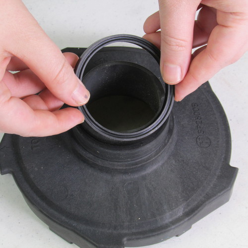
Remove the old O-ring and install the new O-ring on the diffuser assembly as shown.
Step 34
Insert the diffuser assembly on to the seal plate assembly as shown. Again be sure to align the top to top orientation. It should say "top" on the diffuser.
Step 35
Install new body o-ring on the pump wet end assembly as shown.
Step 36
Set the power unit next to the wet end assembly as shown and slide it in.
Step 37
Insert the four 9/16" by 1 3/4" stainless steel bolts as shown and tighten with a 9/16" wrench.
Step 38
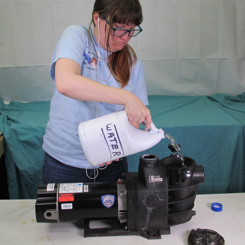
Always fill the pump with water
before running (a gallon or 2 is enough)
STEP BY STEP INSTRUCTIONS
For the purpose of this demo, We have removed the front wet end and brought it to the bench. In an actual senario, the front housing would remain in the pool owners yard, still connected to the plumbing
All these images are in HighDefinition
Right Click and open in new tab for a close
up inspection
These instructions apply to model numbers: SP2600X5, SP2605X7, SP2607X10, SP2610X15, SP2615X20, SP2621X25, SP2607X102S, SP2610X152S, SP2615X202S, SP2800X5, SP2805X7, SP2807X10, SP2810X15, SP2815X20, SP2810X152