\
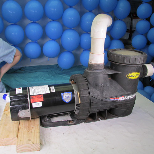
How to change the motor & seals on a
Jacuzzi Magnum & Magnum Plus & Cantar
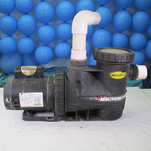
Step by Step Instructions
These images are in Hi-Def Format
You can view in full resolution by right
clicking on image & opening in new tab
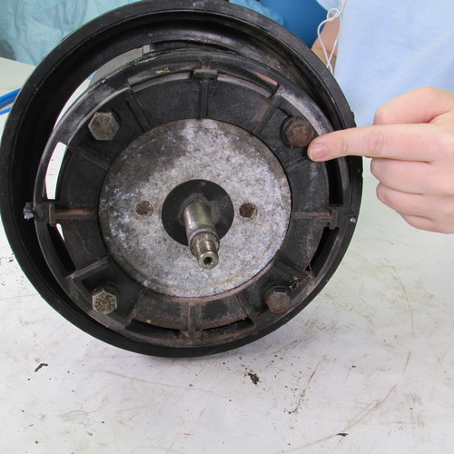
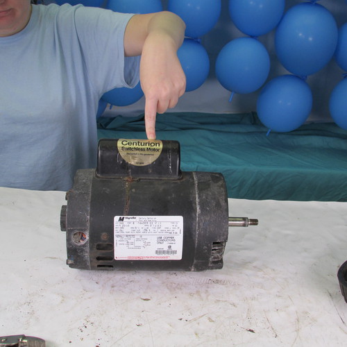
Step 1
We must remove the rear cap to gain access to the shaft. We must do this to lock the shaft from turning.
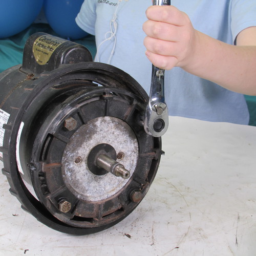
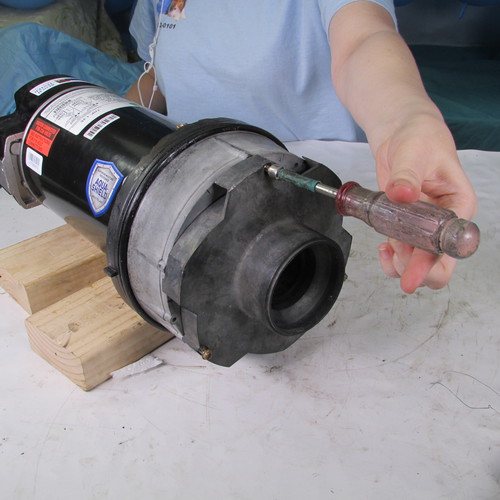
Step 2
On this pump to lock the shaft we insert vice grip locking pliers as shown. Other motors may use different methods for locking the rear shaft.
Step 3
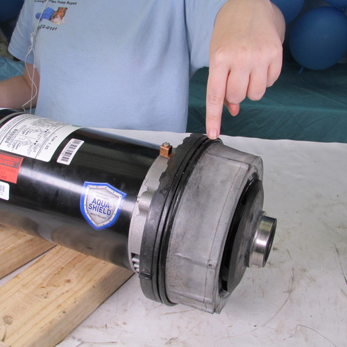
Next we will remove the yellow plastic locking tab on the seal plate mounting ring. Some of the older pumps will have this plastic locking tab missing.
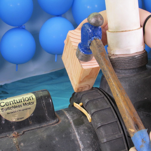
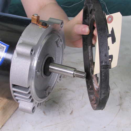
Step 4
Next we will remove the seal plate locking ring by rotating it in a counter clockwise direction. If it will not turn by hand then we insert a block of wood onto one of the ribs and gently tap it loose with a hammer. The key word is gently. If you use too much force you can split the plastic locking ring.
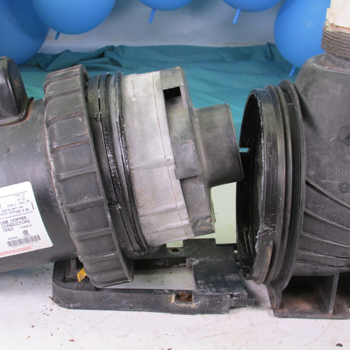
Step 5
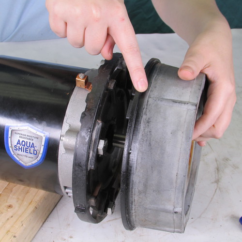
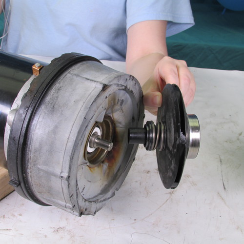
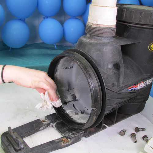
Once the locking ring is removed then we move the power unit containing the motor rearward. It will usually pull out gently however if it is stubborn you may have to pry it back with two small screwdrivers. Be very careful that you do not damage the O-ring seal mating surfaces.
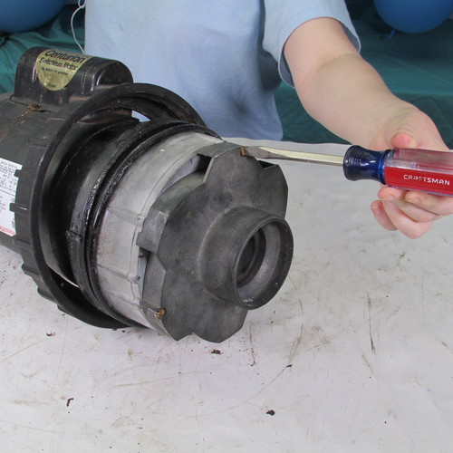
Step 6
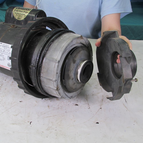
Next we will remove the 3 screws holding the diffuser to the seal plate as shown. Twist these screws in a counter clockwise direction to remove them.
Step 7
Use the appropriate tools as needed it is usually a Philips head or hex head quarter inch driver.
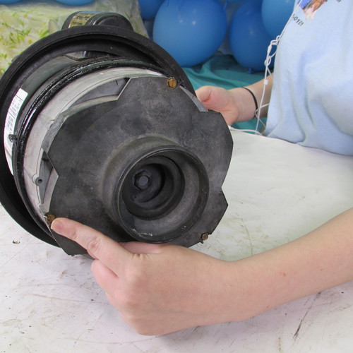
Step 8
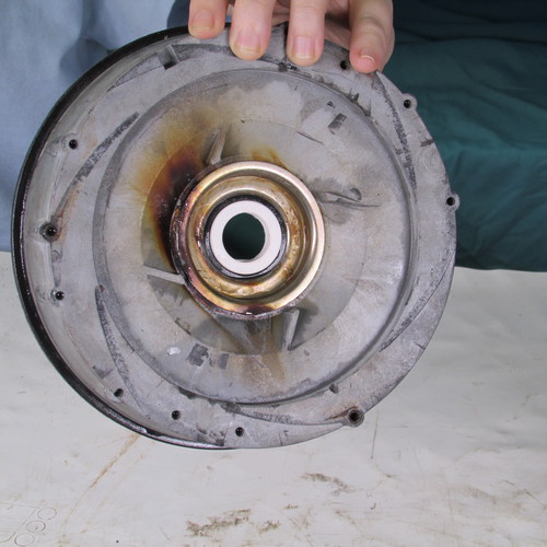
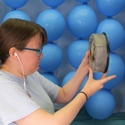
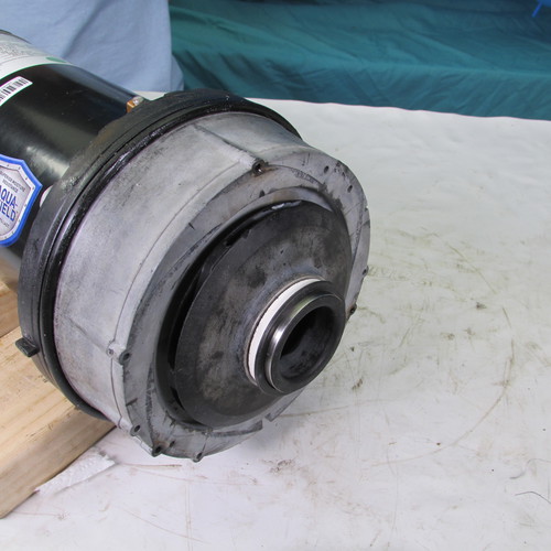
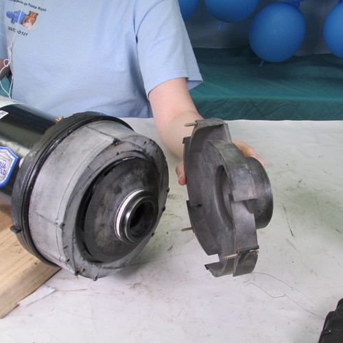
Gently pull it away as shown. Inspect for any damage such as cracks or warping
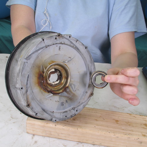
Step 9
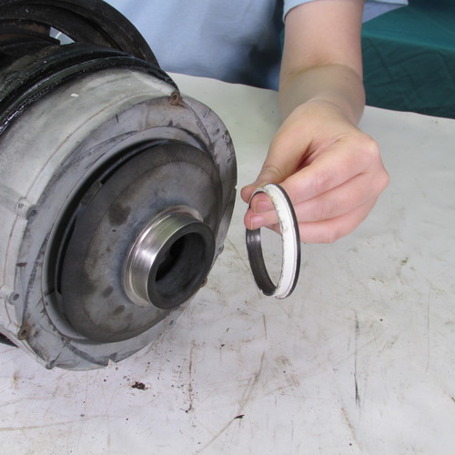
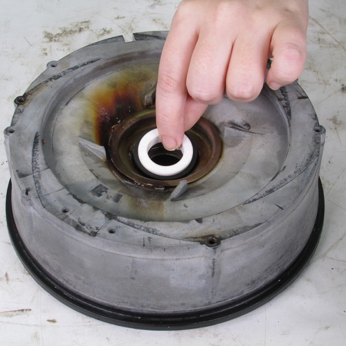
Remove the floating eye ring as shown. Note that the larger side of the ring is pointed outward.
Step 10
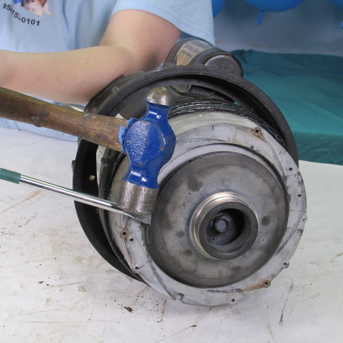
Next we will remove the impeller this is done by rotating it in a counter clockwise or left direction. You can use a set of very large channel locks or a strap wrench. Always grasp the impeller by the large outer diameter. Do not put any tools on the small protruding nose of the impeller as this will break very easily. A method that we have found to be very sucessful for removing an impeller is to insert the blade of a large flat bladed screw driver into the outer edge of the impeller and strike the screw driver close to the impeller in a counter clockwise direction with a hammer. The resulting impact force will usually break free the most stubborn impeller. Then we simply twist the impeller off in a counter clockwise direction. Always use proper body and eye protection when using these tools.
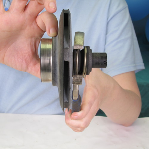
Step 11
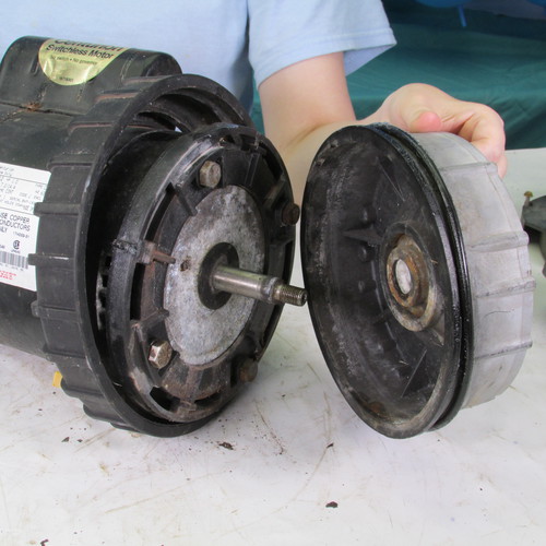
Next we remove the seal plate from the seal mounting ring by sliding it forward as shown.
Step 12
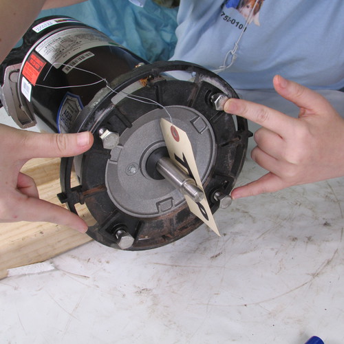
Next we will remove the four mounting bolts that attach the ring to the motor.
Bolt 1
Bolt 2
Bolt 3
Bolt 4
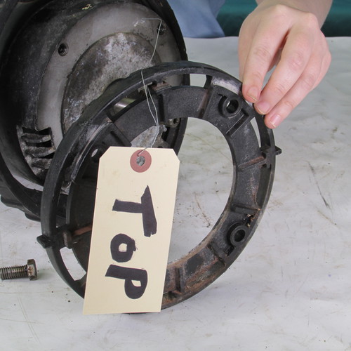
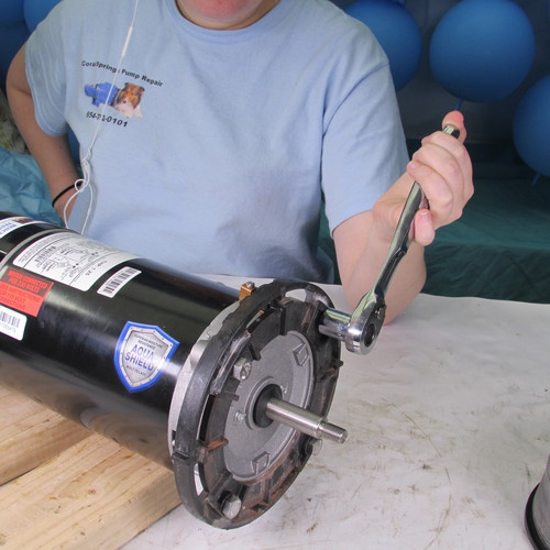
One method of removing these bolts is to use a 9/16" ratchet wrench however you may have to tap the handle of the wrench with a mallet or hammer to impact the bolts free. Many times these bolts are stubborn as they are many times made out of carbon steel as opposed to stainless steel and the heads will rust or become deformed. If that is the case and you can not get a socket around the bolt head to grip then an alternative method is to drill out the bolt. Start with a very small drill in the center of the bolt and drill a pilet hole. Then gradually enlarge the size of the hole with successively increasing the drill size until you are up to 3/8 of an inch. then the head of a bolt should be gone and you should be able to remove the mounting ring. Be careful to not crack or break the mounting as it is very fragile. In the event that you enlarge the mounting holes on the mounting holes during the bolt removal process you can usually save the mounting ring upon installation by putting a stainless steel flatwasher under the bolt head. We recommend replacing the bolts with stainless steel bolts.
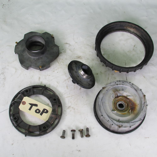
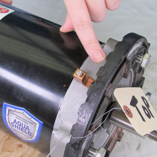
Important: Make note that the ruffled ridges are on the top of the mounting ring and point towards the motor it would be advisable to tag the top f the mounting ring so you can reassemble it properly.
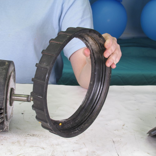
Step 13
Next we remove the seal plate locking ring and set it aside.
Step 14
You can now discard the motor---If you are doing a seal replacement job, you can set the motor aside for reinstallation later
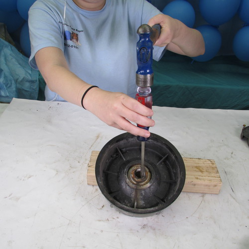
Step 15
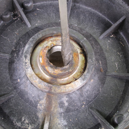
Next we will remove the seal seat assembly from the seal plate. We set the seal plate on a block of wood and insert a screwdriver against the ceramic seat as shown and gently tap the seal seat assembly out of the seal assembly.
Be sure to remove the entire seal seat assembly including the ceramic part and the rubber part. Many people leave the rubber seat on the seal plate which will result in difficulty and confusion when trying to reinstall the seal seat.
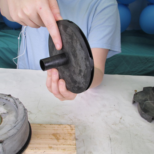
Step 16
Next we will remove the seal head assembly from the impeller tail by grasping the seal head assembly with channel lock pliers and twisting it off in a rotary motion. Hold the impeller securely using leather gloves. Do not hold a impeller with bare hands because it is sharp and you could get cut.
Many times the seal head assembly will break into pieces when you are attempting to remove it, it is very important to remove all pieces and remnants of the seal head assembly.
Step 17
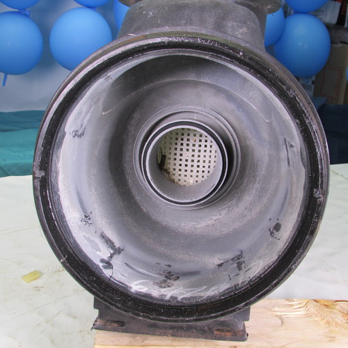
Next we want to wash all the parts with soap and water in preparation for reassembly.
It is very important to pay attention to the seal seat bore as shown and be sure it is clean and free of debris.
Do the same thing with the impeller tail be sure there is no grease or oil on this part.
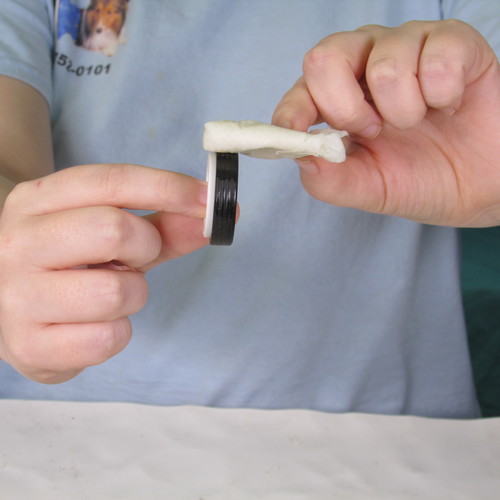
Step 18
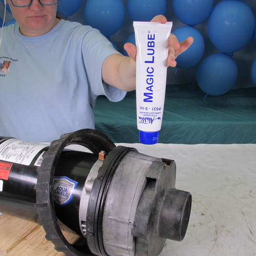
Next we will lubricate the seat of the new seal with soap and water. Do not use grease, oil, WD40, Magic Lube, Teflon, or silicone grease. A rubber lubricant such as P80 or US Seal lube is ok but most homeowners do not have these available there for water and soap is an acceptable substitute.
Step 19
We insert the seal seat assembly into the bore of the seal plate with the white part up.
Step 20
Next using the rounded butt of a clean screwdriver gently press the seal seat assembly into the seal plate as shown.
Step 21
Carefully and thoroughly inspect the seal seat assembly to make sure it is inserted correctly and not crooked or cocked.
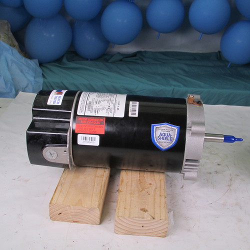
Step 22
Next unbox the new motor or get the old motor you set aside before if you're only doing a seal replacement job
Step 23
Next we will install the seal plate mounting ring onto the face of the new motor. Notice the orientation is such that the top that we marked previously will go to the top of the new motor. If your new motor had a capacitor cover or hump on the top then at this time it would be advisable to install the pump body locking ring, just slide it on the motor behind the motor mounting ring. if your motor does not have the capacitor hump as shown then you can do this later.
Step 24
Next replace the four 9/16" bolts with new stainless steel bolts.
Step 25
Double check the orientation of the mounting ring and verify that the ruffles are at the top and the ruffles point towards the motor as shown. If you installed it incorrectly remove it and reinstall it again at this point.
Step 26
Tighten the four motor mounting bolts as shown.
Step 27
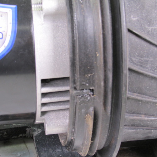
Next we will install the seal plate assembly on to the motor mounting ring. Notice that there are two key slots one at the top and one at the bottom and it will only go on one way. Do not force this part on if it doesn't go on easy. Recheck the orientation if that occurs.
Step 28
Close up of key slot.
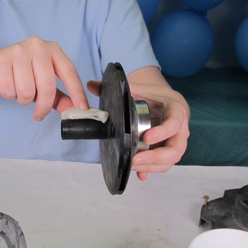
Next we lubricate the tail of the impeller with soap and water. Do not use grease, oil, WD40, Magic Lube, Teflon, or silicone grease. A rubber lubricant such as P80 or US Seal lube is ok but most homeowners do not have these available. Therefore water and soap is an acceptable substitute.
Step 29
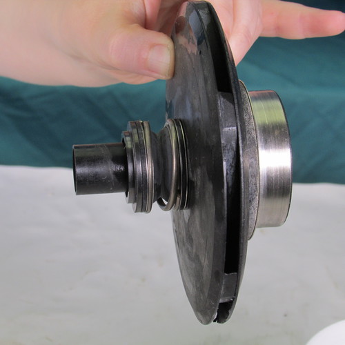
Slide the new seal head assembly on to the tail of the impeller as shown. Assemble it as shown.
This is what it should like look when its done make sure the seal head is butted up against the impeller back as shown.
Step 30
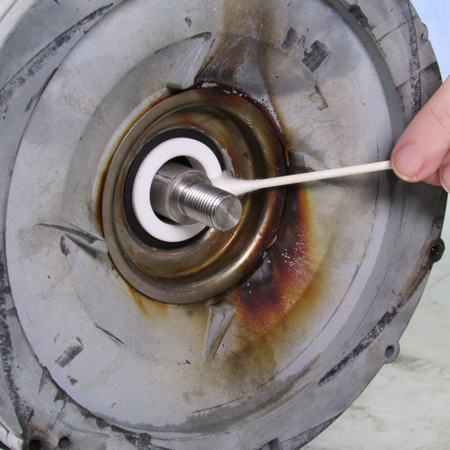
VERY IMPORTANT
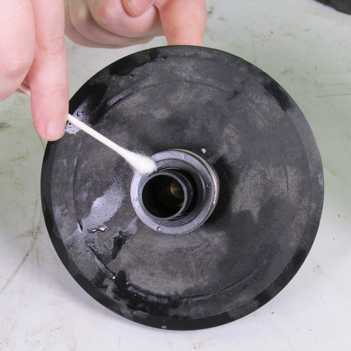
Using a cotton swab saturated in rubbing alcohol carefully clean the seal seat assembly as shown. Do not omit this step in the interest of time because it is very important that the seal mating surfaces be very clean.
Step 31
VERY IMPORTANT
Using a cotton swab saturated in rubbing alcohol carefully clean the seal head assembly as shown. Do not omit this step in the interest of time because it is very important that the seal mating surfaces be very clean.
Step 32
Reinstall the impeller by inserting it on to the shaft as shown.
Step 33
Tighten the impeller in a clockwise direction. Hand tight is sufficient however do not tighten it with bare hands as shown always use leather gloves as impellers can be sharp. It is usually not necessary to lock the shaft at the rear of the motor if the impeller seats on the shaft, however if you are not sure if it is seated, simply remove the rear cover and lock the motor shaft with a wrench
Step 34
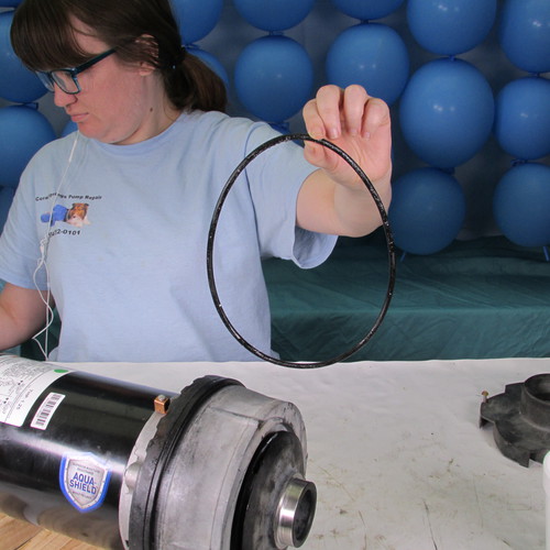
Replace the body O-ring as shown. Reinstall the O-ring you can use Magic Lube.
Step 35
Insert the impeller eye ring onto the impeller as shown make sure the larger side of the impeller eye ring is outward as shown.
Step 36
Next we will reinstall the diffuser as shown and tighten the three screws as shown below.
Step 37
Next we will apply a liberal amount of Magic Lube to the mounting O-ring and wet end assembly as shown below.
Step 38
Inspect the diffuser O-ring as shown. It is usually a round square cut O-ring and it is located in the center of the wet end as shown in this picture. Most of the time it is in good shape and will not have to be replaced. However if it is damaged or rotten then it may be advisable to replace it.
Step 39
Slide the power unit assembly into the wet end as shown.
Be sure the power unit firmly seats into the wet end assembly.
Notice the two key ways locking as shown. Make sure the power unit is fully seated before tightening the lock ing ring. Do not try to pull the motor in with the lock ring
Tighten the locking ring assembly in a clockwise direction as shown. This should go on hand tight it should not be necessary to apply and additional force.
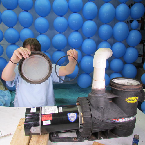
Step 40
Replace the lid O-ring as shown.
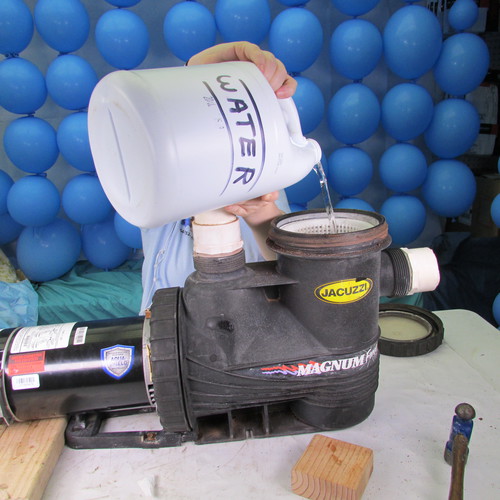
Step 41
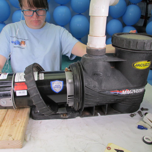
Fill the pump basket with water before running the pump.
For the purposes of this demo, we have removed the wet end assembly and brought it to the workbench. In a real life senario the wet end will usually remain connected to the pool plumbing and stay on the equipment slab in the pool owners yard