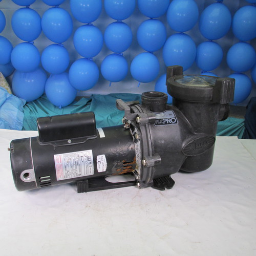
How to change the motor & seals on a
Jandy Zodiac Flo Pro Pool Pump
Step by Step
These images are in a Hi Resolution
Format and may be expanded by right clicking on them and opening in a new window. This will allow close inspection
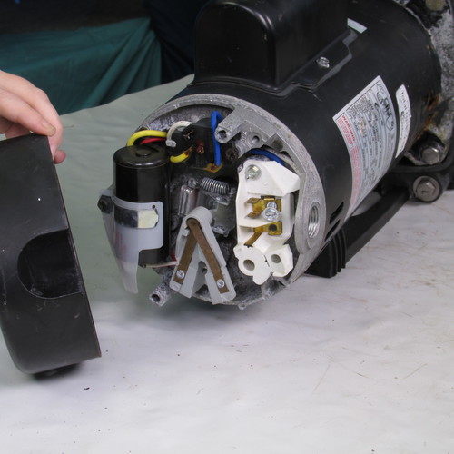
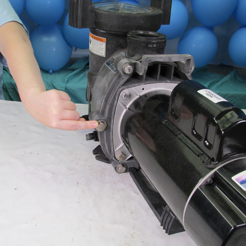
Step 1
The first thing we do is remove the two screws holding on the back cover of the motor.
Gently remove the rear cover. Sometimes it is stubborn and you may have to tap it with a screwdriver or chisel at the seams.
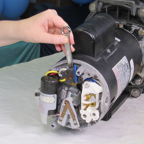
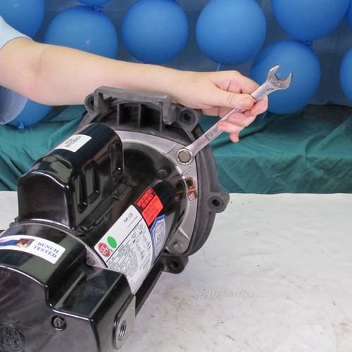
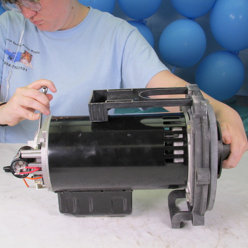
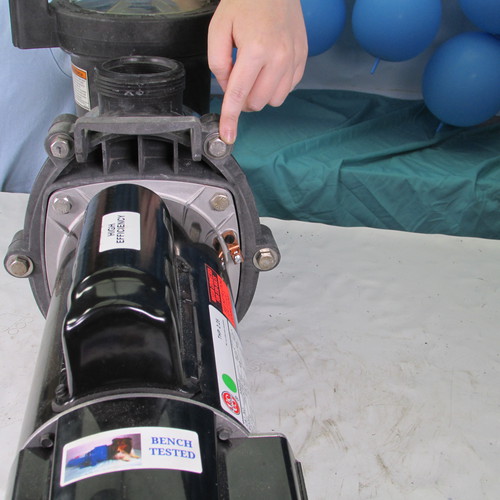
Step 2
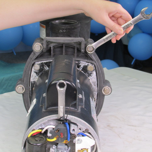
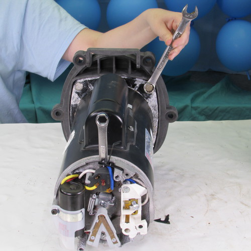
Insert a 7/16" open end wrench behind the overload protector as shown and slide it downward to lock the shaft.
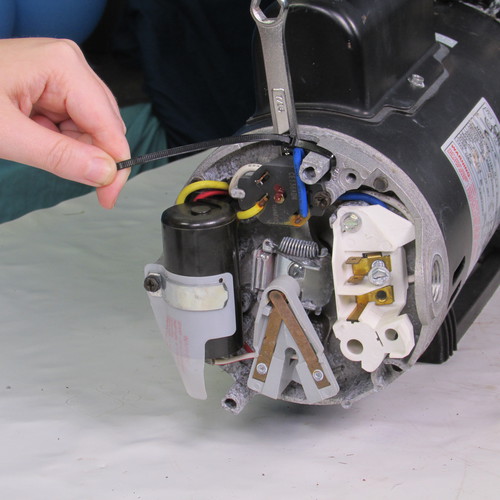
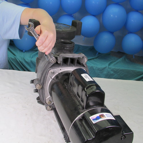
Step 3
Next we will use a zip tie to lock the 7/16" wrench to the motor post as shown. This will prevent the wrench from falling out.
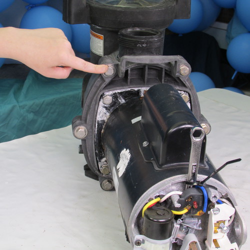
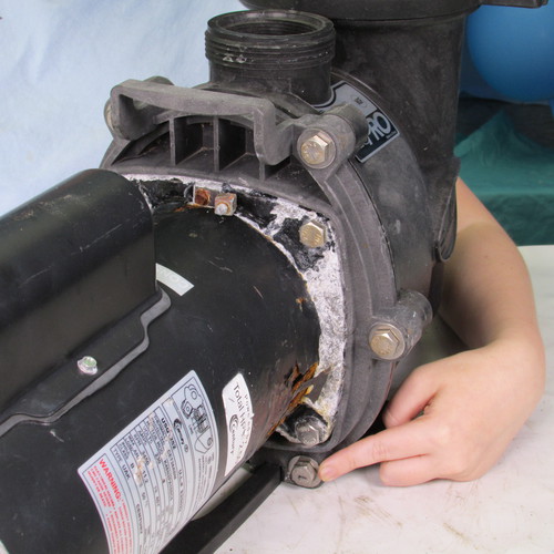
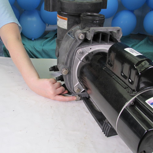
In the next step we will remove the six 9/16" stainless steel bolts as shown. These six bolts are located around the periphery of the seal plate.
Bolt 1
Bolt 2
Bolt 3
Bolt 4
Bolt 5
Bolt 6
Do not remove these four bolts at this time
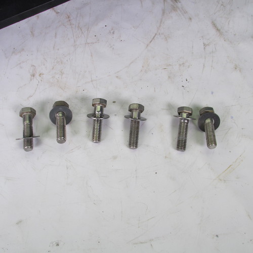
A 9/16" wrench is used to remove the bolts in a counter clockwise direction.
Set the six bolts aside to be used later in reassembly.
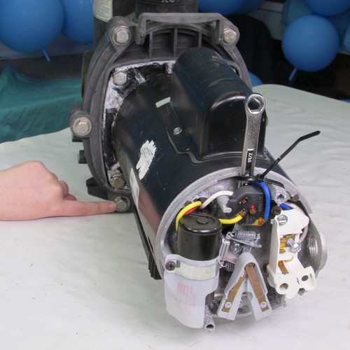
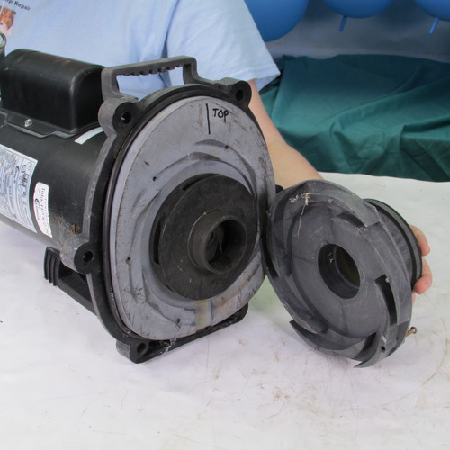
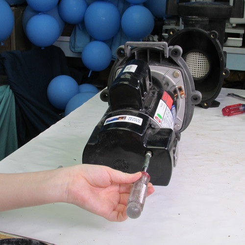
Step 4
Gently pry apart the rear power unit from the wet end assembly using a couple screw drivers as shown. For the purpose of this demonstration we have removed the wet end of the pump and placed it on the work bench. In a real life scenario the wet end will stay attached to the pool plumbing and sit on the equipment slab in the pool owner's yard.
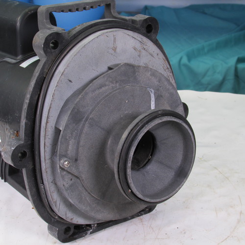
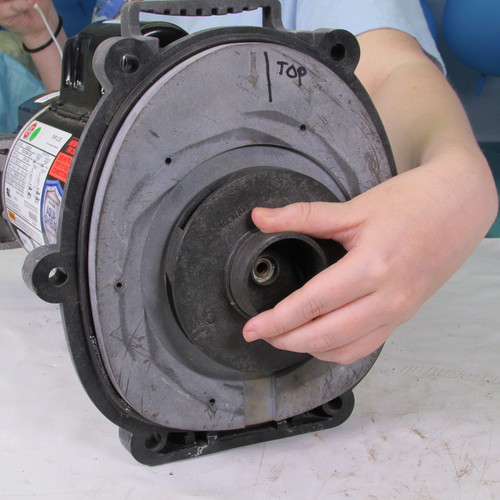
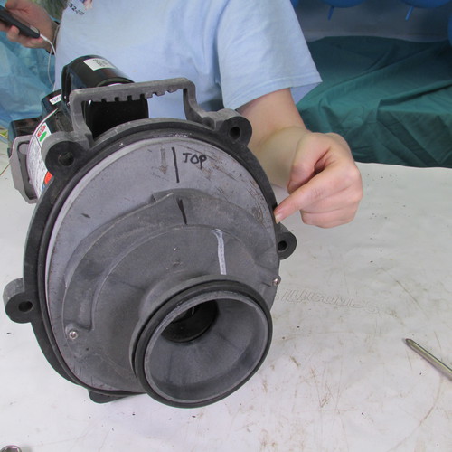
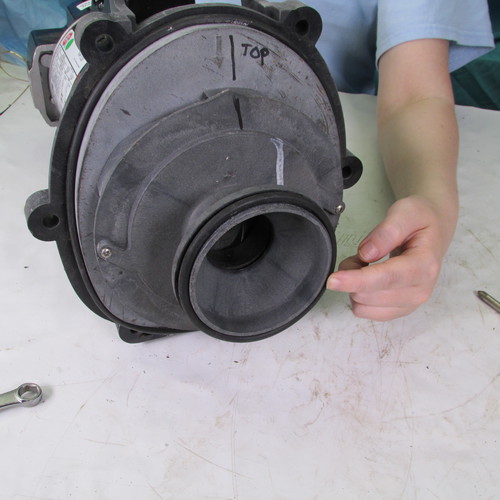
Step 5
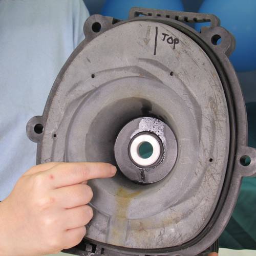
Using a marker put two lines on the diffuser and seal plate and indicate the top position by writing the word "top" on the seal plate. This will make reassembly easier later on.
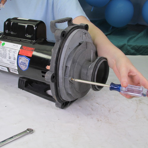
Step 6
Remove the two diffuser screws as shown. They twist off in a counter clockwise direction.
Step 7
Gently pull the diffuser away from the seal plate and set it aside as shown.
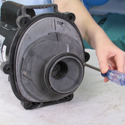
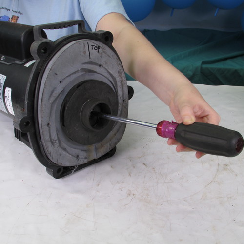
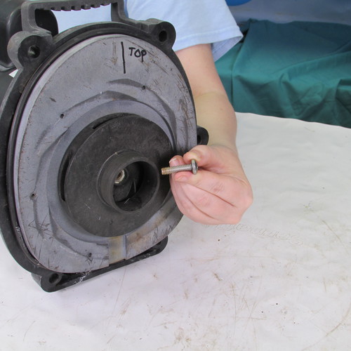
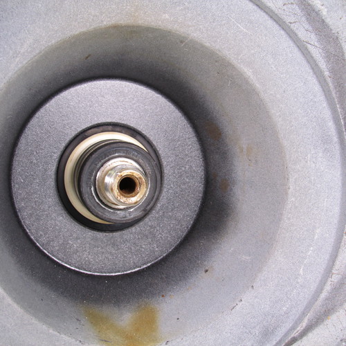
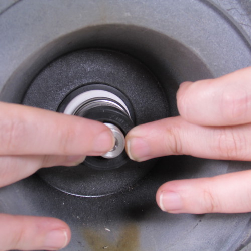
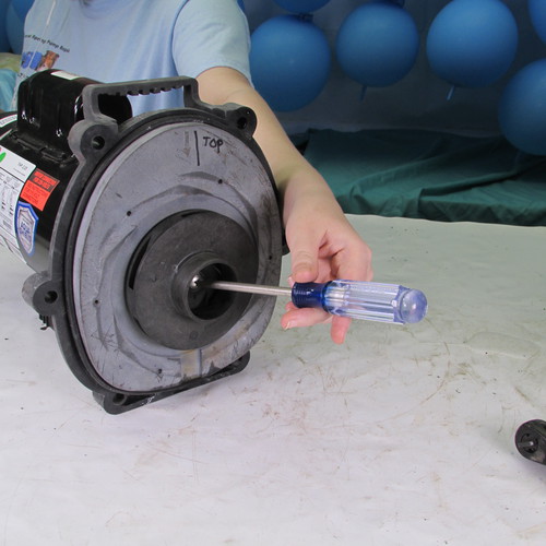
Step 8
Next we must remove the impeller locking screw. This screw is unique in that it is a left handed thread also known as a reverse thread. That means to loosen it you must turn it right or in a clockwise direction.
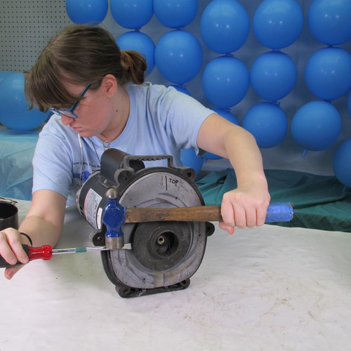
Step 9
The next step is to remove the impeller. This is achieved by rotating it in a counter clockwise or left direction. This can be done by using a strap wrench on the outer diameter of the impeller or using very large channel lock pliers on the outer diameter. Do not use any tools on the small nose of the impeller as this will result in it breaking. A method that we found very good for removing the impeller is to simply insert the blade of a large flat bladed screw driver into the outer edge of the impeller and then strike the screw driver with a metal hammer. The resulting impact force will usually free up the most stubborn impeller without damaging it. Once the impeller is freed up simply rotate it in a counter clockwise direction by hand until it comes off. Always use appropriate body and eye safety equipment when using these tools.
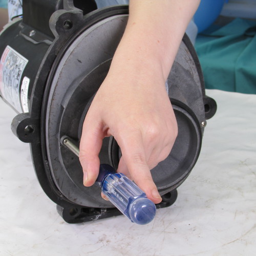
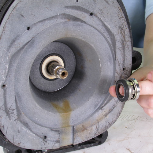
Step 10
At this point we need to remove the seal head assembly. This is accomplished by using two large flat bladed screw drivers as shown.
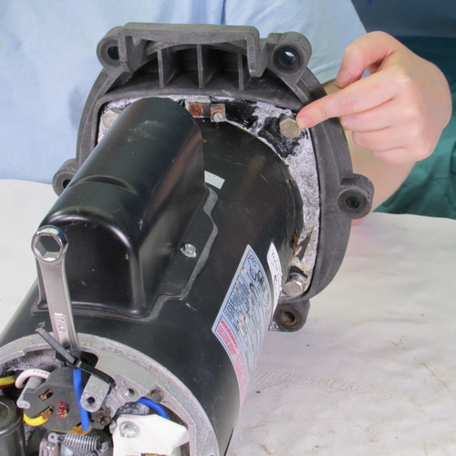
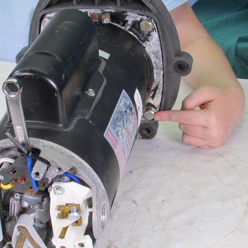
Step 11
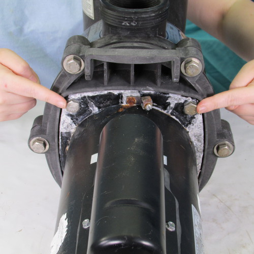
We will remove the four motor mounting bolts as shown.
Bolt 1
Bolt 2
Bolt 3
Bolt 4
These are removed with a 9/16" wrench by turning them in a counter clockwise direction. Sometimes they may be stubborn and it may be necessary to impact the wrench by striking it with a mallet or block of wood. The resulting impact force should loosen up the bolts.
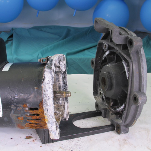
Step 12
Once the bolts are removed we simply slide the seal plate away from the motor. At this point the motor can be discarded however if you are only replacing the seals then put the motor aside for reinstallation later.
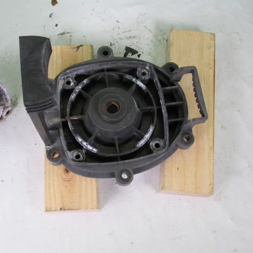
Step 13
Set the seal plate on a couple blocks of wood as shown.
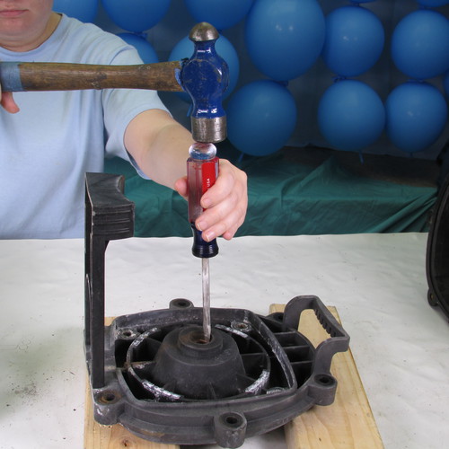
Step 14
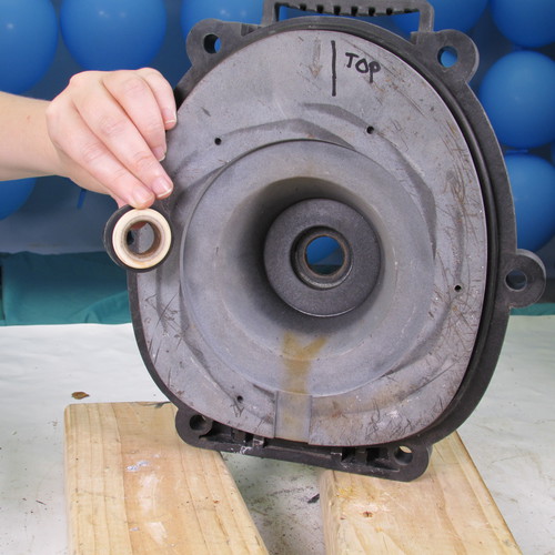
Using a hammer and strong flat bladed screw driver gently tap the seal seat out of the seal plate as shown.
This is what the seal plate and seal insert should look like. Be sure to remove both parts of the seal seat that includes both the ceramic white portion and black rubber part.
Step 15
Make a thorough inspection of the seal plate assembly pay particular attention to the bore of the seal seat. This is the round area where the seal seat was installed. Check to be sure there is no evidence of melting that was caused by overheating. The surfaces should be smooth and square. Do not use a seal plate that is damaged or deformed. If the plate is good, this is excellent time to wash it with soap and water in preparation for reassembly
Step 16
Next we will reinstall the seal seat assembly. We can lubricate it with soap and water. Do not use WD40, grease, oil, Magic Lube, or any petroleum product. Do not use silicone.
Step 17
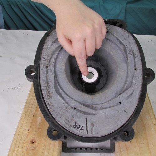
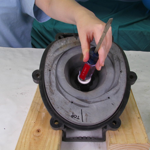
Place the seal seat in the bore of the seal plate as shown.
Using the rounded butt of a screwdriver gently press the seal seat into the seal plate as shown.
Step 20
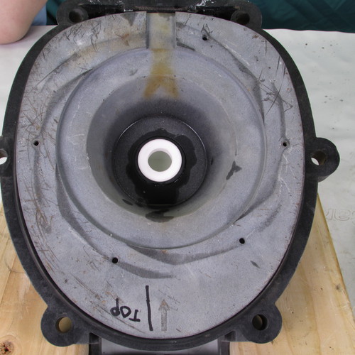
VERY IMPORTANT
At this point it is critical to be sure the white seal seat face is clean. It is best to clean it using rubbing alcohol using a soft cloth or cotton swab.
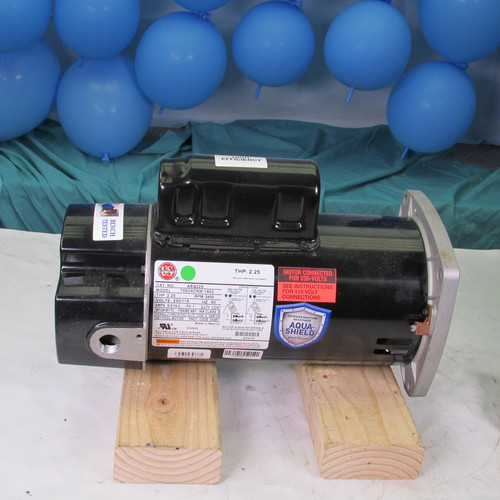
Step 21
Unbox the new motor and place it on a couple of blocks as shown.
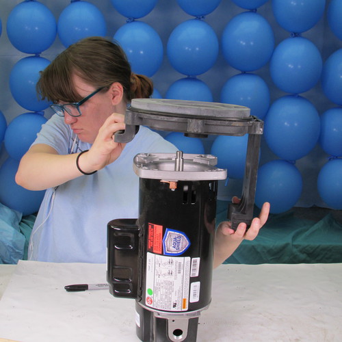
Step 22
Place the seal plate on to the front flange of the motor as shown. Be very careful so that the motor shaft end does not make contact with the white ceramic seal seat during installation. Do this procedure very slowly and carefully.
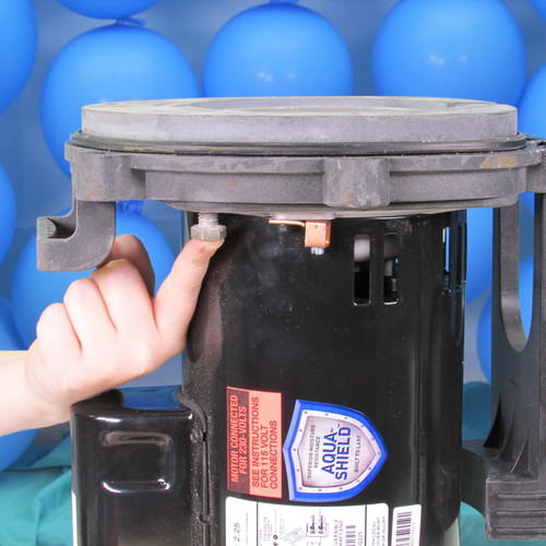
Step 23
Next we will reinstall the four 9/16" seal plate bolts that we removed previously.
Tighten them up with a 9/16" wrench in a clockwise direction.
Step 24
Once again using a cotton swab saturated with alcohol we will clean the seal head assembly and the white ceramic seal seat assembly. It is very important that both these surfaces be very clean upon reassembly.
Step 25
Place the seal head assembly on to the shaft as shown. Be very careful that the black carbon portion of the seal does not make contact with the motor shaft as this could damage it. Gently press the seal head assembly on to the shaft as shown. The seal head bore can be lubricated with soapy water if necessary. But do not use grease, oil, WD40, Magic Lube, or silicone.
Step 26
Next we reinstall the impeller by turning it in a clockwise direction. Hand tight is sufficient at this point.
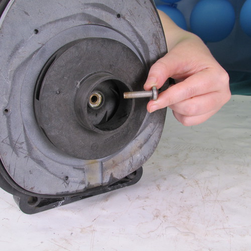
Step 27
Next we insert the impeller lock screw. Remember that this screw is a left hand thread so in order to tighten it you must turn it to the left or counter clockwise direction.
Tighten the screw with an appropriate tool
Remove the back cover from the new motor.
Using a 7/16" wrench lock the shaft of the motor as shown.
Step 28
While holding the 7/16" wrench with one hand use the other hand to tighten the impeller in a clockwise direction hand tight is sufficient.
Step 29
Step 30
Reinstall the back cover as shown.
Step 31
Slide the diffuser on to the impeller as shown.
Tighten the screws with a screwdriver.
Step 32
It is best to replace the O-rings on the seal plate and diffuser as shown. It is ok to lubricate these O-rings with Magic Lube.
Step 33
In the next step we slide the rear power unit assembly with the motor into the front wet end assembly. (In most situations the wet end assembly will be located on the equipment slab in the yard. But for this demo we have removed it and brought it to the work bench.)
Step 34
We will reinstall the six 9/16" stainless steel bolts that we removed previously.
Bolt 1
Bolt 2
Bolt 3
Bolt 4
Bolt 5
Bolt 6
We tighten these bolts with a 9/16" wrench in a clockwise direction.
Step 35
Fill the pump with water a gallon or two is sufficient. Never let a pump run dry.
Step 36
Replace the O-ring on the basket cover lid. This can be lubricated with Magic Lube.
This instruction set applies to these models: FHPM.75, FHPM1.0, FHPM1.5, FHPM2.0, FHPM2.5, FHPM1.0-2, FHPM1.5-2, FHPM2.0-2